
A pipeline or well can need both a temperature profile and vibration information. That does not make DAS and DTS interchangeable, or make every sensing cable suitable for both. Start with the measurement and then specify the optical path, cable construction and installation.
Distributed acoustic sensing vs distributed temperature sensing
Silixa’s DAS technology explanation describes dynamic strain recovered from the phase of Rayleigh backscatter. “Acoustic” should not be read as a promise that a fiber is a calibrated microphone. The reported quantity, units and processing depend on the instrument and measurement configuration.
| Selection question | DAS | Raman DTS |
|---|---|---|
| Primary measurement | Dynamic strain-related response along the sensing path | Temperature profile along the sensing path |
| Common optical principle | Coherent Rayleigh backscatter, often phase-based | Temperature-dependent Raman backscatter |
| What must reach the fiber? | Mechanical deformation associated with the event | The thermal condition of the monitored location |
| Typical project questions | Where is vibration occurring? Does its signature meet an event criterion? | Where is the route warmer or cooler? How does temperature change over time? |
| Important setup fields | Gauge length, sampling, bandwidth, response units and processing | Calibration, integration time, spatial resolution and temperature uncertainty |
| Cable and installation concern | Strain transfer, mounting, directionality and background noise | Thermal contact, jacket response and environmental exposure |
| Fiber compatibility | Single-mode is common; confirm the instrument specification | Multimode is common; single-mode options depend on the instrument |
The Raman DTS principles explain temperature evaluation and fiber considerations. Other distributed sensing techniques also exist; these two columns do not classify every Rayleigh or Brillouin instrument. For slowly varying deformation and temperature cross-sensitivity, see our separate DTS vs distributed strain sensing guide.

Why the cable construction and placement matter
For DAS, specify how strain reaches the fiber. Cable placement, attachment, surrounding material and internal construction form a mechanical path. A protective structure that allows fiber movement may behave differently from a strain-coupled structure. Protection against installation load and transfer of a small dynamic signal are separate design requirements. Ask for a response check using the proposed installation rather than treating “armored” as a sensitivity specification.
For DTS, specify what temperature the fiber represents. Fiber temperature can lag or differ from the process temperature because of the thermal path through the jacket, mounting and environment. Protection, chemical resistance and response time must be considered together. Record the monitored location and response criterion in addition to a maximum operating-temperature value.
A fiber route can also cross different soils, supports or process conditions. Mark these transitions on the route drawing and keep the optical-distance-to-asset-location map. Use the DTS installation guide for routing and commissioning records, and the bend-radius guide for cable-specific routing limits.
Can DAS and DTS share one cable or fiber?
One cable: a project may specify separate sensing fibers in a common cable, provided their types, routing, mechanical behavior, optical losses and termination are suitable. Confirm the design; do not assume that adding spare cores resolves the different sensing requirements.
One fiber: this needs an explicitly supported optical architecture. Wavelengths, launch power, filters, backscatter requirements and interrogation schedules can matter. Get written compatibility from the instrument suppliers before connecting systems together. A cable supplier’s fiber count is not proof of multi-instrument interoperability.
Pipeline example: vibration events and thermal anomalies
Consider a hypothetical pipeline project that wants to locate mechanical disturbance and track a temperature profile. Treat these as two acceptance questions. A temperature anomaly may support investigation of a process change; a vibration signature may support event classification. Neither measurement by itself establishes a universal leak-detection guarantee.
- Define the purpose. Identify the thermal change and mechanical event of interest, the required location accuracy and the decision the result will support.
- Agree the optical plan. Record instrument model, compatible fiber, route length, core allocation, splices and termination.
- Agree the transfer path. Specify placement and attachment, including sections with different surroundings or construction.
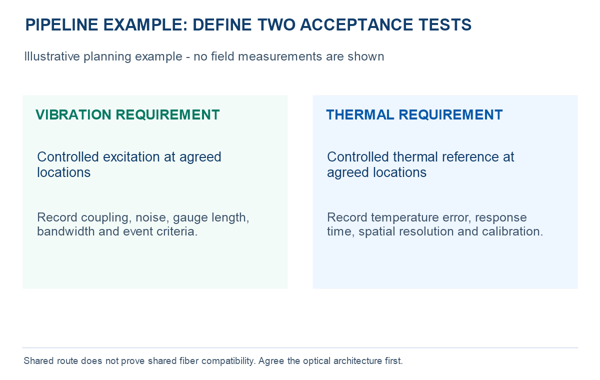
- Validate each measurement. Use agreed controlled thermal references and mechanical excitation under the site’s approved procedure. Record noise and environmental conditions.
- Preserve the baseline. Keep route mapping, optical loss results, settings and measurement records for comparison after maintenance.
What to include in a sensing-cable RFQ
- Measurement: DAS, Raman DTS, strain sensing or a defined combination; target quantity and acceptance method.
- Instrument interface: interrogator make/model, fiber type, wavelengths, loss budget and allowed connector configuration.
- Environment: operating and installation temperatures, pressure, fluids, chemicals, water exposure and expected mechanical loads.
- Installation: route drawing, attachment method, bend limits, tensile conditions, splices and location references.
- Supply and records: cable length, cores, termination, quantity, optical test records and required installed-response evidence.
For a thermal downhole requirement, start with oil-well temperature sensing fiber optic cable and send the actual pressure, temperature and fluid conditions. For a vibration-monitoring project, use the cable family directory to begin a construction review. Do not infer DAS qualification from a DTS product name. Our DTS fundamentals guide covers the thermal-monitoring workflow in more detail.
Frequently asked questions
Is DAS the same as DTS?
No. DAS commonly measures dynamic strain-related signals; Raman DTS provides temperature along the fiber. Their instruments, optical compatibility and installed transfer paths differ.
Does DAS directly measure sound pressure?
Do not assume it does. Many DAS systems recover a strain-related response over a gauge length. A pressure or acoustic interpretation needs a defined transfer function and calibration.
Can standard telecom fiber be used for sensing?
Some instruments can use compatible existing fiber. Confirm optical performance, access and installed coupling. An optically usable telecom route may not have the mechanical or thermal response required by the project.
Does an OTDR trace prove sensing performance?
No. Optical continuity and loss testing are important, but installed sensing response, calibration and event criteria need separate verification.
Specify the Measurement Before the Cable
Send the interrogator details, route, environment and required thermal or vibration response. OpticLumos can review the cable construction and identify which compatibility and acceptance points need confirmation.
Technical guide published November 9, 2026. Diagrams are conceptual; no installed response, third-party instrument compatibility or leak-detection performance is implied.