
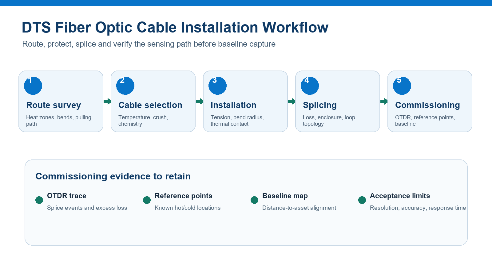
A distributed temperature sensing system can only locate heat accurately when the installed sensing fiber remains optically sound, thermally coupled to the asset and correctly mapped to distance. Cable routing, splice placement and commissioning records therefore matter as much as the interrogator specification.
1. Plan the sensing route before selecting cable
Start with the temperature questions the system must answer: the normal range, alarm thresholds, required detection distance, response time and the physical location that each measured distance must represent. Mark heat-transfer interfaces, cold lead-in sections, penetrations, joint boxes, valves, bends, transitions and areas where the cable may be inaccessible after installation.
Define whether the cable is strapped to a pipe, embedded in concrete, installed in a capillary, clamped to busbar or power equipment, deployed downhole, or routed through a tray. These arrangements impose different requirements for thermal coupling, crush resistance, tensile strength, diameter, chemical protection and repair access. The DTS principles and cable selection guide explains Raman, Brillouin and Rayleigh system differences; this article focuses on field installation and acceptance.
2. Match cable construction to the installation load
| Installation condition | Construction priority | What to confirm | Common failure to avoid |
|---|---|---|---|
| Pipe, tank or fire-detection route | Reliable thermal contact, crush protection and manageable bend radius | Attachment spacing, jacket compatibility, alarm-zone mapping and exposure temperature | Loose routing that delays heat transfer or moves the cable away from the monitored surface |
| Oil well or high-pressure capillary | Metal-tube protection, pressure sealing, hydrogen resistance and high-temperature materials | Continuous/peak temperature, pressure, tube OD, gel/fill, feedthrough and termination method | Quoting only a temperature value while omitting pressure, chemistry and deployment tension |
| Power cable or electrical equipment | Dielectric behavior, flame performance, mechanical protection and routing clearances | Voltage environment, sheath material, fire requirement, grounding constraints and accessories | Assuming a metal-armored construction is acceptable in every electrical installation |
| Tunnel, conveyor or long industrial route | Pulling strength, flame/smoke requirement, repair access and zone identification | Drum length, pulling method, joint locations, cable tray fill and local code | Placing avoidable splices in inaccessible or high-risk areas |
| Concrete or structural monitoring | Crush protection, strain isolation where required and durable position fixing | Pour sequence, tie method, minimum bend radius and as-built coordinates | Allowing cable movement during the pour and losing the distance-to-location map |
The sensing fiber, buffer, strength member, armor and outer sheath work as one mechanical and thermal system. A tougher cable may survive installation but respond more slowly if additional layers impede heat transfer. A small cable may respond quickly but require a protected route. Do not select on outer diameter or maximum temperature alone.
3. Control installation tension, bending and thermal contact
Use the manufacturer’s pulling limit
Plan the pull length, route friction, rollers, winch control and pulling attachment so short-term tensile load stays within the cable specification. Do not pull through connectors or improvised fiber ends.
Respect dynamic and static bend radii
The installation bend limit can differ from the long-term limit. Check sheaves, tray corners, enclosure entries, coiled slack and the finished route. Microbending may add loss without an obvious break.
Fix the sensing section consistently
For surface temperature monitoring, use an attachment method and spacing that maintain predictable thermal contact without crushing the cable. Document insulation placed above the sensor and any deliberate thermal isolation.
Separate sensing and lead-in sections
Record non-sensing lead lengths, patch cords, launch fiber and routing outside the monitored zone. The interrogator measures optical distance, so all fiber before the asset shifts the reported position.
4. Design splice locations and channel topology
Minimize unnecessary joints, but do not trade away maintainability. Put splice enclosures where they remain accessible and compatible with temperature, moisture, pressure and chemical exposure. Record fiber type, splice loss, enclosure ID, route distance and the cable segment on both sides.
Single-ended Raman DTS normally uses one accessible fiber end; loop configurations may support double-ended measurements or continuity strategies depending on the interrogator. The IEC 61757-2-2 description distinguishes single-ended and loop configurations for distributed temperature measurement. Confirm topology with the instrument vendor before ordering cores or assigning return fibers.
- Fiber type and coating compatibility
- Fusion-splicer program and protection sleeve
- Measured bidirectional or agreed splice loss method
- Enclosure sealing and strain relief
- Splice distance from the interrogator and corresponding asset location
- Reserved fibers and loop mapping
5. Commission the complete optical and thermal path
Commissioning should prove continuity, optical quality, route mapping and temperature response. Test the installed cable before connecting it to the interrogator, then store results with the as-built drawing. OTDR traces are useful for locating reflective events, high-loss splices and unexpected bending, but they do not by themselves prove DTS temperature accuracy.
| Evidence | Purpose | Record |
|---|---|---|
| Continuity and end-face inspection | Prevents avoidable launch and connector problems | Channel ID, connector condition and cleaning status |
| OTDR trace at agreed wavelength(s) | Locates events and creates an optical baseline | Launch setup, range, pulse width, index setting and trace file |
| Known hot/cold reference | Aligns optical distance to a physical point and checks response | Reference location, temperature, duration and reported distance |
| Distance-to-asset map | Turns alarm distance into an actionable field location | Route chainage, cable slack, splices, loop turn and asset labels |
| System baseline | Supports future comparison after maintenance or damage | Temperature profile, instrument settings, date and environmental state |
Evaluate accuracy, repeatability, spatial resolution, temperature resolution, response time and measurement range under the chosen instrument configuration. IEC 61757-2-2 defines performance parameters and test approaches for distributed temperature measurement; procurement documents should state the parameters that matter to the project rather than using “high accuracy” as an acceptance criterion.
Application-specific checks
Oil wells and high-temperature sensing
Define continuous and peak temperature separately, together with pressure, hydrogen exposure, deployment method, metal tube dimensions, wellhead feedthrough and retrieval expectations. Review the oil-well temperature sensing cable and high-temperature cable selection guide for material choices.
Fire and industrial hot-spot detection
Map alarm zones to accessible landmarks and test representative hot spots after final cable fixing. The cable’s flame, smoke and environmental requirements must follow the applicable project code; a DTS function does not replace cable fire qualification.
Power cable monitoring
Coordinate sensor placement with joints, terminations and high-load sections. Confirm whether metallic protection is permitted and whether the design requires dielectric cable. Record cable crossings and spare loops because they can create multiple temperature locations at similar route distances.
DTS installation and cable RFQ checklist
- DTS method and interrogator model; wavelength and channel topology
- Total route and drum lengths, lead-in length, loop/return arrangement and spare fibers
- Continuous/peak temperature, pressure, moisture, chemicals, hydrogen and radiation if relevant
- Installation method, pulling load, crush exposure, bend limits and required cable OD
- Required metal tube, armor, strength member, sheath and flame/smoke performance
- Splice and termination locations, feedthroughs, connectors and enclosure constraints
- Thermal-contact method and target response time
- OTDR, splice-loss, route-mapping and temperature-reference acceptance records
- As-built drawing, serialized cable/drum identification and baseline file format
Frequently asked questions
Can standard telecom fiber be used for DTS?
Many Raman DTS systems use multimode sensing fiber and some other distributed systems use single-mode fiber, but compatibility depends on the interrogator and required range. The cable construction must also survive the installation environment. Confirm both the optical fiber and the finished cable.
Does a smaller sampling interval mean better spatial resolution?
No. Sampling interval is the spacing between reported data points. Spatial resolution describes the ability to distinguish temperature events along the fiber and is influenced by the instrument and measurement settings.
Why is an OTDR trace needed if the DTS unit shows temperature?
An OTDR trace provides an independent optical baseline and helps locate splices, reflections, bends and excess loss. It complements, rather than replaces, thermal commissioning.
Should DTS cable be installed in a loop?
Only when the interrogator, redundancy plan and measurement method support that topology. Confirm the channel plan first and document the loop-turn distance.
References
Need a DTS cable and installation review?
Send the interrogator, route, temperature, pressure, chemistry, mechanical loads, topology and acceptance plan. OpticLumos can review the cable construction and prepare a project-specific quotation.