
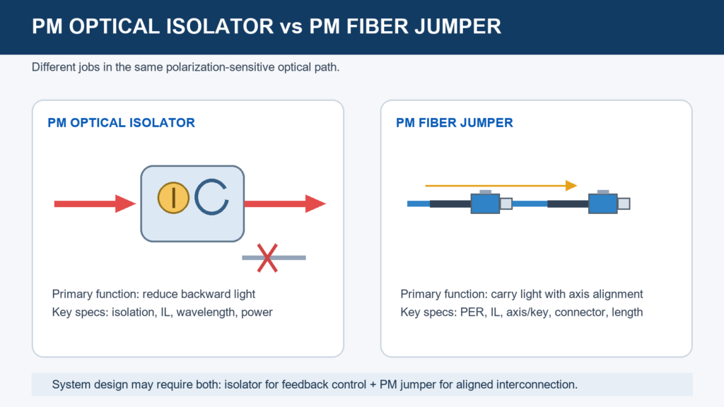
A PM optical isolator and a PM fiber jumper can sit next to each other in a laser or sensing system, but they perform different jobs. One suppresses reverse optical feedback; the other transports a polarization-aligned signal between components.
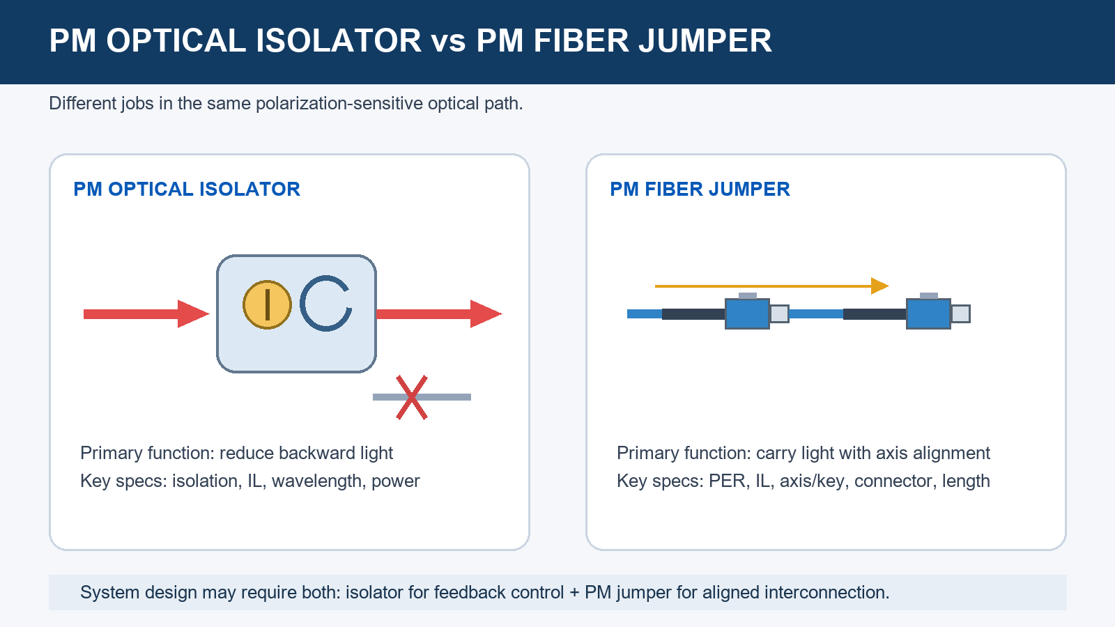
The functional difference
PM optical isolator: control reverse propagation
An optical isolator is a non-reciprocal device. A Faraday rotator and polarizing elements transmit light in the intended direction while strongly attenuating light returning toward the source. This reduces feedback that can destabilize a laser or, at higher returned power, damage the source. The transmission arrow and input/output direction therefore matter.
PM fiber jumper: preserve a chosen polarization axis
A PM jumper connects two optical ports using high-birefringence fiber, commonly PANDA-style fiber. When the input linear polarization is correctly aligned to a principal axis and the cable is installed within its limits, the fiber reduces coupling between the slow and fast axes. The jumper does not create one-way transmission and does not protect a laser from back-reflected light.
Isolation and PER measure different things
Isolation (dB)
Compares reverse power entering an isolator with reverse power that reaches its input. Higher isolation means stronger rejection in the blocked direction. It is specified over a wavelength and temperature range and can change with alignment and power conditions.
PER / extinction ratio (dB)
Compares optical power in two orthogonal polarization axes after a defined launch and measurement. Higher PER indicates less cross-coupled power. System PER is limited by the weakest component and by connector alignment, splices, bends and input polarization.
A jumper can have high PER while providing essentially no isolation. An isolator can provide high reverse isolation while an attached cable introduces axis misalignment and reduces system PER. Treat both as separate rows in the system budget. The PER guide explains measurement and system contributors.
How to specify a PM optical isolator
| Parameter | Selection question | Why it matters |
|---|---|---|
| Center wavelength and bandwidth | What are the source wavelength, tuning range and temperature shift? | Faraday rotation and coatings are wavelength dependent. |
| Isolation | What minimum reverse rejection is needed across the band? | Protects the source from expected feedback. |
| Forward insertion loss | What loss can the power budget accept? | The isolator consumes forward power. |
| Optical power | State average, peak and pulse conditions. | Power handling depends on optical format and internal materials. |
| Fiber and polarization | PM fiber, SM fiber or free space? Which axis? | Determines coupling, orientation and package. |
| Return loss/connectors | Connectorized, pigtailed or free-space? PC or APC? | Interface reflections remain part of the system. |
| Environment | Temperature, size, vibration and mounting? | Isolation and alignment must hold in the installation. |
Single-stage and dual-stage isolators trade package complexity, insertion loss and isolation. Do not choose stage count from a generic rule; compare guaranteed isolation and loss at the required wavelength, temperature and power.
How to specify a PM fiber jumper
- Match fiber to wavelength and mode field. “PM fiber” alone is incomplete. State the fiber designation and operating/test wavelength.
- Define connector and polish at both ends. FC/PC and FC/APC are different mating interfaces; hybrid jumpers must name end A and end B.
- Define key-to-axis orientation. Slow-axis key alignment is common, but the required axis and angular tolerance belong on the drawing.
- Specify assembly PER, IL and RL. Record test wavelength, launch condition, mating reference and acceptance value.
- Control mechanics. State length, jacket/tubing, bend radius, routing, boot and temperature. Stress can reduce installed system PER.
Review the polarization-maintaining fiber guide and the PM fiber jumper selection guide. A standard starting point is the PANDA PM fiber jumper, with final performance agreed for the wavelength and termination.
When the system needs both
The isolator faces in the forward propagation direction and supplies the reverse-feedback barrier. The jumpers carry the aligned state into and out of the device. Each connector interface can add loss, reflection and angular error, so the assembled path must be budgeted as a system.
Narrow-linewidth seed laser
Select the isolator from seed wavelength, tuning range, backward power and permitted forward loss. Select the jumper from source pigtail fiber, connector, slow-axis convention, PER target and routing. High jumper PER cannot compensate for inadequate isolation; high isolation cannot correct a 90-degree key/axis mapping error.
Interferometric sensor
The isolator protects the source, while the jumper controls fiber type, axis, connector polish and mechanical stress. The verification plan should measure reverse isolation separately from jumper PER and insertion loss.
Comparison table
| Question | PM optical isolator | PM fiber jumper |
|---|---|---|
| Primary function | Reject reverse-propagating light | Connect ports while preserving aligned polarization |
| Directional? | Yes; observe input/output arrow | Usually reciprocal, though end definitions may differ |
| Headline metric | Isolation and forward insertion loss | PER, insertion loss and return loss |
| Critical inputs | Wavelength, bandwidth, power and port format | Fiber, wavelength, axis and connectors |
| Can replace the other? | No | No |
System selection and RFQ checklist
For the isolator supplier
- Center wavelength, bandwidth and temperature range
- Minimum isolation and maximum forward insertion loss
- Average/peak power and pulse conditions
- PM, SM or free-space ports; fiber and axis convention
- Connector/polish, return loss, package and direction
For the PM jumper supplier
- End-A and end-B fiber/connector definitions
- Operating and test wavelength
- Slow- or fast-axis key alignment and angular tolerance
- Minimum PER, maximum insertion loss and minimum return loss
- Length, tubing, bend radius, labels and test report
For paths combining several passive elements, the custom passive optical components guide helps organize interfaces and acceptance requirements. Connector families are listed under optical components and connectors.
Frequently asked questions
Does a PM fiber jumper protect a laser from back reflection?
No. A PM jumper transports light and preserves axis alignment; it does not provide the non-reciprocal rejection of an isolator.
Is isolation the same as PER?
No. Isolation quantifies rejection in the reverse direction. PER quantifies the power ratio between orthogonal polarization axes under a defined launch and measurement.
Should the FC connector key align to the slow axis?
Slow-axis-to-key alignment is common, but it must be confirmed for every component and written into the system drawing. Mixing conventions can rotate the launch by 90 degrees.
Can system PER be lower than the jumper test value?
Yes. Input alignment, connector angular error, splices, other components, bending and stress can reduce system PER.
References
- Newport — Faraday Isolator User’s Guide
- Thorlabs — High-ER PM patch cables and measurement notes
- IEC 61300-3-4:2023 — attenuation measurement
Need a PM jumper matched to your optical chain?
Send the fiber type, wavelength, connector/polish, key-to-axis convention, length and acceptance limits. OpticLumos can review the jumper interface and prepare a custom assembly quotation.