
Polarization extinction ratio (PER) is a key performance metric for polarization-maintaining fiber, pigtails, patch cords, laser systems, interferometers, and polarization-sensitive photonic components. Expressed in decibels, it compares optical power in the intended polarization axis with power that has coupled into the orthogonal axis. A higher PER generally indicates cleaner polarization separation—but a meaningful specification must always include wavelength, launch alignment, fiber length, bends, connectors, test method, and environmental conditions.
Quick answer: Polarization extinction ratio is calculated as PER (dB) = 10 log10(Pdesired / Porthogonal). A measured value is a system result, not only a property of the bare fiber. Launch alignment, axis orientation, splices, connectors, mechanical stress, temperature, and instrument quality can all change the result.
Engineering takeaways
- Never compare PER values unless wavelength, length, test setup, and delivered configuration are comparable.
- Specify assembly-level PER when purchasing a pigtail, patch cord, cable, or connectorized component.
- High bare-fiber birefringence cannot compensate for poor launch alignment or incorrect connector keying.
- When troubleshooting, isolate the source, launch optics, fiber, splices, connectors, bends, and detector one step at a time.
What is polarization extinction ratio?
Polarization extinction ratio describes how effectively an optical signal remains in one linear polarization state relative to the unwanted orthogonal state. In a polarization-maintaining (PM) fiber system, light is normally aligned with either the slow axis or the fast axis. Imperfect alignment or coupling transfers some power to the other axis, reducing PER.
PER is frequently used to evaluate PM fiber assemblies, polarized laser outputs, modulators, sensors, interferometers, and other polarization-sensitive systems. It is related to polarization purity, but it is not the same as birefringence, beat length, degree of polarization, polarization-dependent loss, or polarization mode dispersion.
Polarization extinction ratio formula
The common power-ratio definition is:
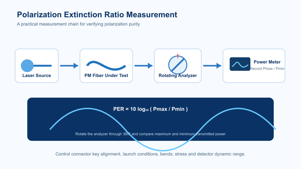
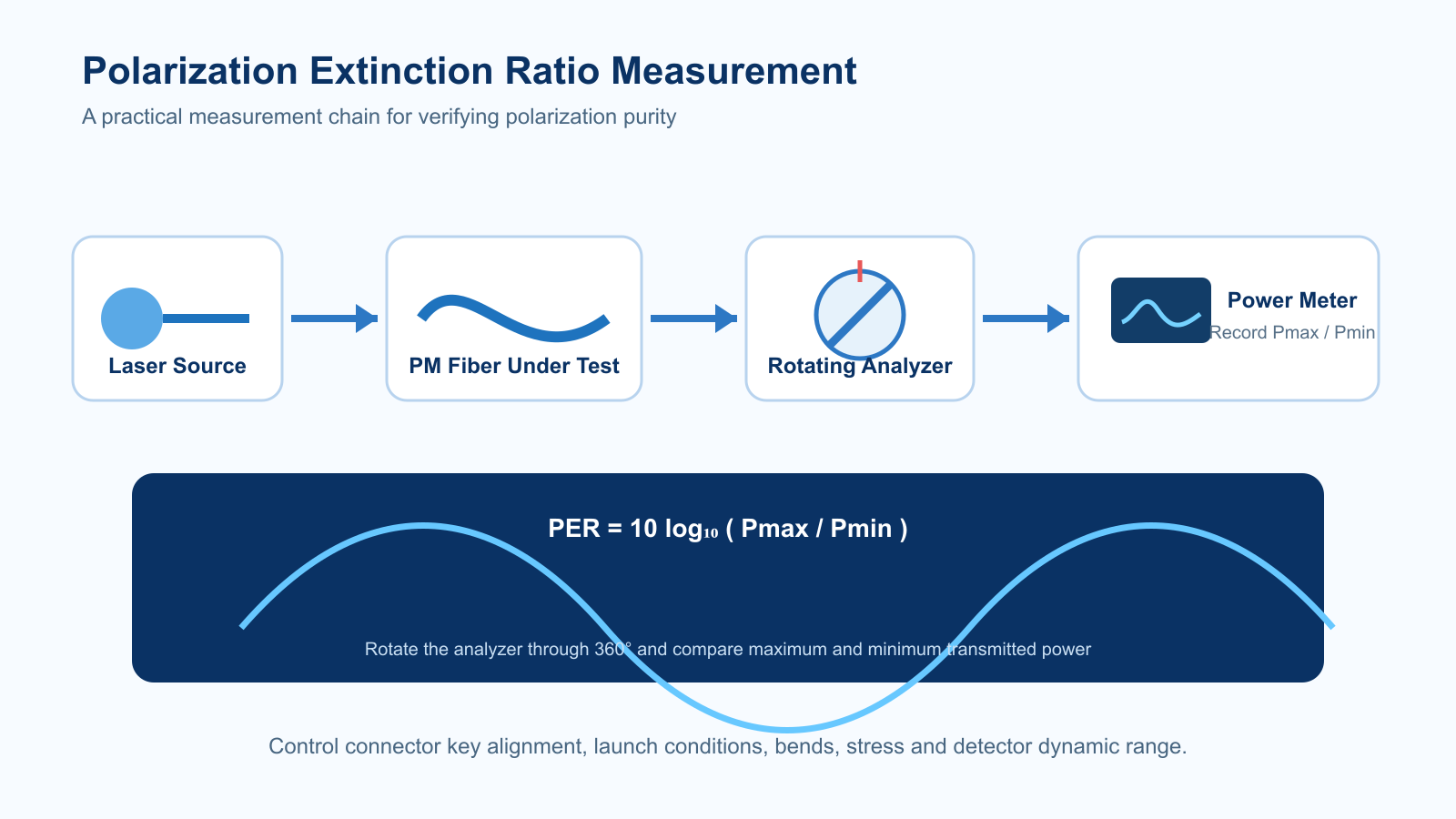
PER (dB) = 10 log10(Pmax / Pmin)
Here, Pmax is the detected power when the analyzer is aligned with the dominant polarization, and Pmin is the detected power at the orthogonal analyzer position. Depending on the instrument and test method, the labels may also be written as Pdesired and Porthogonal.
| PER | Power ratio | Orthogonal power relative to desired power |
|---|---|---|
| 10 dB | 10:1 | 10% |
| 20 dB | 100:1 | 1% |
| 30 dB | 1,000:1 | 0.1% |
| 40 dB | 10,000:1 | 0.01% |
These conversions are mathematical examples, not acceptance limits. The required PER depends on system sensitivity, measurement uncertainty, packaging, operating environment, and the performance budget allocated to each component.
Worked PER example: 30 dB does not mean zero leakage
If the desired-axis power is 1 mW and the orthogonal-axis power is 1 µW, the ratio is 1000:1 and PER is 30 dB. The orthogonal power is 0.1% of the desired-axis power. This is a mathematical example, not a product guarantee; the instrument must resolve the minimum power accurately.
PER vs related polarization specifications
| Parameter | What it describes | Why it is not interchangeable with PER |
|---|---|---|
| Birefringence | Difference between effective refractive indices of two principal axes | It is a fiber property; PER also depends on launch and assembly conditions. |
| Beat length | Distance over which the phase difference accumulates by one complete cycle | It indicates birefringence strength, not the delivered polarization purity by itself. |
| Cross-talk | Unwanted coupling between orthogonal axes, often normalized to a stated length | Definitions and test lengths vary; the sign convention may also differ. |
| Degree of polarization | Fraction of total light that is polarized | Highly polarized light may still contain an unwanted orthogonal linear component. |
| Polarization-dependent loss | Change in component insertion loss with input polarization | It characterizes loss variation, not axis power separation. |
How is polarization extinction ratio measured?
Rotating-analyzer method
A linearly polarized source is coupled into the device or fiber under test. At the output, a polarizer or analyzer is rotated while optical power is recorded. The maximum and minimum detected powers are used in the PER formula. The method is conceptually simple, but detector dynamic range, background light, analyzer extinction ratio, source stability, and angular resolution limit accuracy.
Polarimeter-based measurement
A polarimeter measures the output polarization state and calculates polarization parameters. This can provide faster characterization and additional information, but the wavelength range, calibration, detector sensitivity, fiber movement, and assumptions used by the instrument still matter.
Extinction-ratio meter
Dedicated PER meters are often used for production tests. Buyers should record the instrument model, wavelength, test configuration, averaging, uncertainty, and pass/fail criteria so results from different locations can be compared.
Recommended PER measurement workflow
- Stabilize the source. Confirm wavelength, output power, polarization state, and warm-up conditions.
- Clean and inspect interfaces. Contaminated connector end faces can add loss and unstable readings.
- Establish a reference. Measure the source and reference path before inserting the device under test.
- Align the input axis. Optimize slow-axis or fast-axis launch without exceeding bend or stress limits.
- Fix the test geometry. Document fiber length, coil diameter, connector orientation, splices, and strain state.
- Measure maximum and minimum power. Ensure the minimum reading is above the instrument noise floor.
- Repeat the measurement. Reconnect or realign when appropriate to quantify repeatability.
- Record environmental conditions. Temperature, vibration, cable routing, and handling can affect sensitive assemblies.
What affects polarization extinction ratio?
Launch-angle error
When input polarization is not aligned with a principal axis, both axes are excited. Even a well-designed PM fiber can show disappointing PER if launch alignment is inaccurate.
Connector key orientation
PM connectors must be keyed to a defined slow- or fast-axis orientation. Angular errors, ferrule rotation, poor end-face geometry, contamination, or adapter tolerances can reduce assembly performance.
Fusion-splice axis alignment
Splicing PM fiber requires clear identification and alignment of the stress structure or principal axes. Cleave quality, arc program, concentricity, rotational alignment, and splice protection all contribute to the final result.
Bending, clamping, and packaging stress
Tight bends, uneven cable clamps, adhesive shrinkage, thermal expansion, or package pressure can modify local birefringence and cause coupling. Test the delivered cable or assembly in a configuration representative of use.
Wavelength and spectral width
Fiber modal behavior, component performance, detector response, and analyzer quality change with wavelength. A specification at one wavelength should not automatically be assumed at another.
Fiber length and environmental variation
Longer paths provide more opportunities for perturbations, splices, bends, and stress. Temperature cycling, vibration, and installation routing may reveal behavior that is not visible in a short laboratory sample.
Troubleshooting low or unstable PER
| Observed issue | Likely checks | Corrective action |
|---|---|---|
| Low PER from the beginning | Source PER, launch alignment, connector key, wavelength | Re-establish the reference and align to the specified principal axis. |
| Reading changes when the cable moves | Bend radius, clamps, cable construction, connector strain relief | Control routing and remove localized stress; test the intended installation geometry. |
| Large difference between laboratories | Instrument floor, analyzer quality, reference method, length and wavelength | Align test procedures and exchange a reference sample. |
| PER drops after splicing | Rotational alignment, splice program, protector stress | Reinspect axis alignment and optimize the splice and protection process. |
| PER degrades with temperature | Package materials, adhesive, cable stress, source stability | Use controlled thermal testing and redesign stress-sensitive packaging if necessary. |
| Minimum power equals instrument floor | Detector noise, stray light and analyzer extinction | Treat the reading as a lower bound or use a higher-dynamic-range setup. |
How to specify PER in a B2B RFQ
A useful RFQ does more than state a single dB value. Include:
- Operating wavelength and spectral width
- Required PER and whether it applies to bare fiber or the finished assembly
- Test length, coil diameter, bend state, and temperature
- Slow-axis or fast-axis launch and connector key orientation
- Fiber type, cladding/coating dimensions, MFD or NA where relevant
- Connector type, polish, pigtail or cable construction, and total length
- Number and type of splices or intermediate components
- Required insertion loss, return loss, and end-face criteria
- Measurement method, wavelength, repeatability, and requested test report
- Quantity, packaging, qualification plan, and delivery schedule
When the required value is close to the test system’s capability, define measurement uncertainty and an agreed acceptance method before production.
Frequently asked questions
Is higher polarization extinction ratio always better?
A higher value indicates greater separation in a specific test, but unnecessarily strict requirements can increase alignment, testing, and assembly cost. Select a value based on the complete system error budget.
What is a good polarization extinction ratio?
There is no universal pass value. Appropriate PER depends on the source, application, wavelength, assembly format, fiber length, environmental conditions, and measurement method. Compare supplier values only under equivalent conditions.
Can standard single-mode fiber maintain high PER?
Standard single-mode fiber does not intentionally preserve a fixed linear polarization. A short, undisturbed section may appear stable temporarily, but PM fiber is normally used when repeatable polarization alignment is required.
Why is connectorized-assembly PER lower than bare-fiber performance?
Connector axis alignment, ferrule rotation, end-face quality, cable stress, handling, and additional interfaces become part of the result. This is why assembly-level acceptance criteria are important.
Are PER and cross-talk the same?
They both describe unwanted polarization coupling, but definitions, sign conventions, normalization, and test length may differ. Always review the supplier’s stated method.
Choose the product format before specifying PER
- PANDA PM fiber jumpers: specify connector key alignment and finished-assembly PER.
- Multicore PM fiber bundle cable: multiple tight-buffered PM fibers in a common reinforced sheath.
- Multicore PM fiber breakout cable: individually sheathed PM subunits for separated routing.
Cable crosstalk specified over a reference length is not automatically a guaranteed PER for a finished connectorized assembly. For connector selection and axis-to-key details, use the PM fiber jumper selection checklist.
Need help defining a PM fiber specification?
Start with our polarization maintaining fiber selection guide, review polarization maintaining fiber options and PM photonic crystal fiber, or send OpticLumos your wavelength, PER target, length, connector, environmental, quantity, and test-report requirements.
Technical content reviewed by the OpticLumos product team. Last updated: September 2026.