
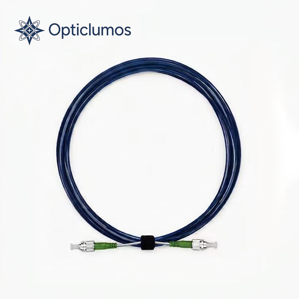
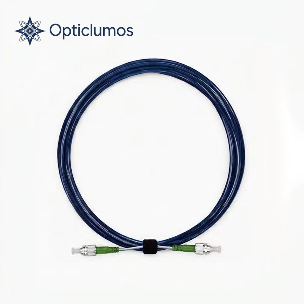
Short answer: Select a polarization-maintaining fiber jumper by matching the operating wavelength and PM fiber first, then define polarization extinction ratio (PER), slow- or fast-axis alignment, connector key width, PC/APC polish, insertion loss, return loss, length and jacket. A PM jumper is not fully specified by “FC/APC, 1550 nm” alone: the connector key must reference the correct fiber axis and the completed assembly should be tested under a stated launch and measurement method.
Polarization-maintaining (PM) fiber jumpers are used in interferometers, fiber gyroscopes, coherent systems, sensors, lasers and test equipment where the polarization state must remain aligned. The most common failure in procurement is treating a PM jumper like an ordinary single-mode patch cord. Connector geometry may look identical while axis orientation and measured PER differ substantially.
PM fiber jumper selection at a glance
| Parameter | What to specify | Why it matters |
|---|---|---|
| Operating wavelength | For example 780, 980, 1064, 1310 or 1550 nm | Determines fiber mode field, cutoff behavior and test condition |
| PM fiber | Panda, bow-tie or required matching fiber | Controls birefringence, beat length and compatibility |
| PER / extinction ratio | Minimum value in dB and measurement method | Quantifies polarization preservation of the assembly |
| Axis orientation | Slow axis or fast axis aligned to connector key | Allows repeatable mating to the intended component axis |
| Connector | FC/PC, FC/APC, LC, SC or custom; narrow/wide key | Affects return loss, rotational repeatability and compatibility |
| Length and protection | Fiber length, buffer, tubing, jacket and bend protection | Affects handling, stress and environmental robustness |
1. Match the PM fiber to the operating wavelength
A PM fiber is designed for a wavelength region. The mode-field diameter, cutoff wavelength, attenuation, birefringence and bend sensitivity must match the source and component. A 1550 nm connector does not make a jumper suitable for 1550 nm if the underlying fiber is optimized for a different band.
When connecting to an existing PM component, request the component’s fiber designation. Matching fiber geometry can reduce splice or butt-coupling loss and make the PER result more predictable.
2. Define polarization extinction ratio correctly
PER is commonly expressed as the ratio, in decibels, between optical power in the intended polarization axis and power in the orthogonal axis. A higher value indicates better separation, but the result depends on launch alignment, source coherence, fiber stress, connectors and test method.
Do not specify “high PER” without a number. State whether the requirement is minimum or typical, the test wavelength, connector state and whether the result applies to the finished jumper. For demanding gyroscope or interferometric applications, ask for an individual test record.
Read the Polarization Extinction Ratio Guide for measurement principles and common error sources.
3. Slow-axis or fast-axis alignment
Panda and bow-tie PM fibers have two orthogonal principal axes. Many commercial jumpers align the slow axis to the connector key, but this must not be assumed. Some systems require the fast axis or a custom angular orientation.
The drawing or purchase specification should define the viewing direction and reference key. For a two-ended jumper, clarify whether both connector keys are aligned to the same fiber axis and how angular error is measured.
4. Connector key width and rotational repeatability
FC connectors are common in PM systems because the key provides a rotational reference. Narrow-key and wide-key versions exist. A narrow-key connector placed in a wide-key slot can rotate more than intended, reducing repeatability and potentially degrading PER. Specify both the plug key and mating adapter/keyway.
5. FC/PC versus FC/APC
FC/PC or FC/UPC uses a perpendicular physical-contact end face. It is widely used in laboratories and systems where return loss requirements are moderate. FC/APC uses an angled end face to reduce back reflection, which is valuable for narrow-linewidth lasers, interferometers and reflection-sensitive systems.
PC and APC connectors must not be mated together. For APC, angular orientation and key repeatability deserve particular attention because the end-face angle must mate correctly.
6. Insertion loss and return loss
Insertion loss depends on fiber matching, lateral and angular alignment, end-face quality and connector condition. Return loss is strongly affected by polish and end-face geometry. State maximum insertion loss and minimum return loss for the completed assembly at the operating wavelength, and define whether measurements are connector-to-connector or include additional components.
7. Length, jacket and environmental requirements
Fiber stress can couple energy between polarization axes. Tight bends, torsion, clamping and thermal changes may reduce measured PER even when the connector alignment is correct. Specify:
- Finished length and tolerance
- Buffer or jacket diameter
- Minimum bend radius
- Operating and storage temperature
- Pull, crush or flex requirement
- Low-outgassing, vacuum, armored or other environmental needs
8. Connectorized jumper or fusion splice?
Connectors provide serviceability but add reflection, insertion loss and rotational tolerance. Fusion splicing can deliver a permanent low-loss joint when the PM axes are actively aligned, but it requires suitable equipment and process control. Systems may combine a connectorized equipment interface with a spliced sensor or component lead.
How to write a PM jumper RFQ
- Application and operating wavelength
- PM fiber type or exact matching-fiber designation
- Minimum PER and test method
- Slow-axis, fast-axis or custom-angle alignment
- Connector types at end A and end B
- Narrow/wide key and mating adapter requirement
- PC/UPC/APC polish
- Maximum insertion loss and minimum return loss
- Length, tolerance, buffer/jacket and bend radius
- Environmental and mechanical requirements
- Individual test report, axis mark and labeling
- Prototype and production quantity
Review the Panda PM Fiber Jumper product page, browse optical components and connectors, or send your wavelength, fiber, PER and connector requirements for technical review.
Common procurement mistakes
- Specifying only connector type and wavelength.
- Assuming every manufacturer aligns the slow axis to the key.
- Ignoring narrow-key versus wide-key compatibility.
- Quoting a typical PER when the project needs a guaranteed minimum.
- Mixing PC and APC interfaces.
- Testing PER without controlling input polarization and fiber stress.
- Using the correct fiber but the wrong mating adapter.
Frequently asked questions
What PER should a PM fiber jumper have?
It depends on wavelength, fiber, connector and application. Values above 20 dB are common, while demanding assemblies may require 25–30 dB or more under a defined test method.
Is the slow axis always aligned to the connector key?
No. It is a common convention, but the axis and viewing direction must be stated on the drawing or purchase specification.
Can a narrow-key FC connector mate with a wide-key adapter?
It may physically mate, but extra rotational play can reduce repeatability. Use a matched key/keyway when axis precision is important.
Should I choose FC/PC or FC/APC?
Choose FC/APC for lower back reflection in reflection-sensitive systems; choose FC/PC/UPC where it matches the equipment and return-loss requirement. Never mate PC and APC directly.
Why can PER change after installation?
Bending, twisting, clamping, temperature, connector rotation and input polarization can couple power into the orthogonal axis and change the measured result.
Technical references
- Thorlabs — Polarization-Maintaining Fiber Patch Cable Selection and Key Alignment
- OZ Optics — Polarization Maintaining Fiber Patchcords and Connectors