
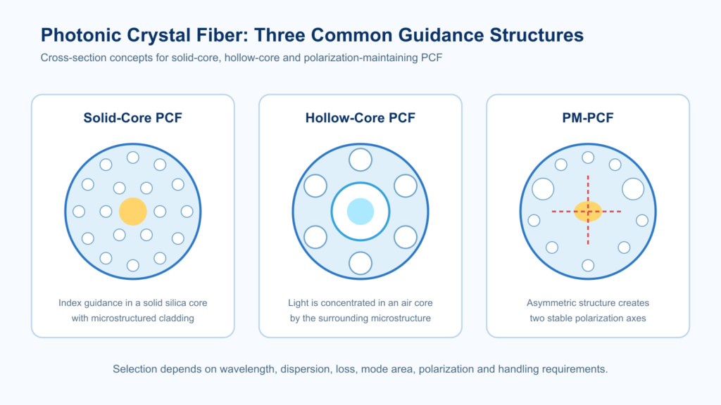
Short answer: Solid-core photonic crystal fiber guides light mainly in silica and is commonly selected when engineers need dispersion control, high nonlinearity, large mode area or unusual modal behavior. Hollow-core fiber guides most optical power in an air-filled core and is considered when low glass interaction, low latency, gas–light interaction or delivery at wavelengths and powers that challenge solid silica are priorities. The better choice depends on wavelength, loss over the required length, mode quality, bend sensitivity, power, dispersion and termination—not on core type alone.
What is the difference between solid-core and hollow-core PCF?
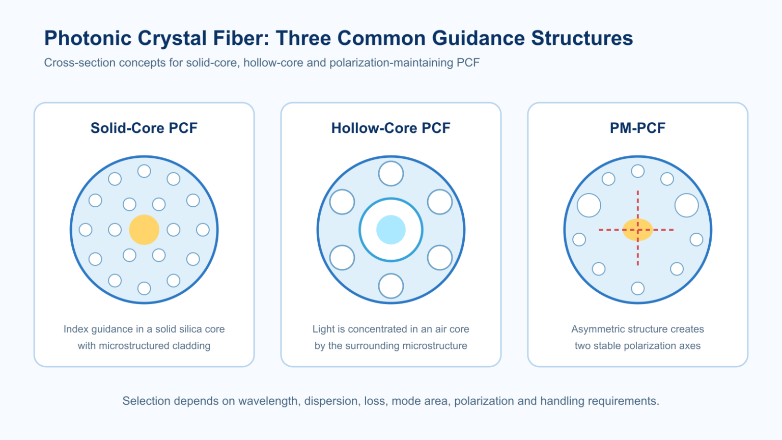
A solid-core photonic crystal fiber normally has a silica core surrounded by a periodic or engineered pattern of air holes. In index-guiding designs, the solid core has a higher effective refractive index than the microstructured cladding. Changing hole diameter, pitch, number of rings and core geometry allows the designer to tailor confinement, dispersion, mode area, birefringence and nonlinear interaction.
A hollow-core fiber contains an air- or gas-filled core. Light is confined by a photonic bandgap, antiresonant reflection or an inhibited-coupling mechanism, depending on the design. Because most optical energy can propagate in the hollow region, interaction with silica is reduced. This can support distinctive properties, but it does not mean every hollow-core fiber automatically has lower loss, higher power handling or better bend performance than every solid-core fiber.
Solid-core vs hollow-core fiber comparison
| Selection factor | Solid-core PCF | Hollow-core fiber |
|---|---|---|
| Where light propagates | Mainly in solid silica | Mainly in an air- or gas-filled core |
| Common guidance mechanism | Modified total internal reflection in index-guiding PCF; other structures also exist | Photonic bandgap, antiresonant or inhibited-coupling guidance |
| Design strengths | Dispersion engineering, high nonlinearity, large mode area, birefringence and modal control | Reduced glass interaction, gas filling, low latency potential and delivery outside common silica windows |
| Key risks to check | Nonlinear threshold, confinement loss, splice loss and microbend/macrobend sensitivity | Transmission-window width, surface-mode effects, bend loss, modal purity and termination complexity |
| Typical interfaces | Fusion splicing or connectorization may be possible with process development | Often requires carefully engineered launch, sealing, end caps or specialty termination |
| Best purchasing approach | Specify optical and mechanical targets at the operating wavelength | Specify the complete system length, bends, launch, environment and gas/sealing requirements |
When should you choose solid-core photonic crystal fiber?
Solid-core PCF is usually the first family to evaluate when the application needs a long interaction length inside glass or a deliberately engineered silica waveguide. Representative use cases include:
- Supercontinuum and nonlinear optics: small effective mode area and tailored zero-dispersion wavelength can increase nonlinear interaction.
- Large-mode-area laser delivery: a larger effective area can reduce intensity while maintaining a controlled mode, subject to bend and launch conditions.
- Dispersion compensation or pulse control: air-hole geometry provides additional design freedom compared with conventional step-index fiber.
- Polarization-sensitive systems: asymmetric structures can produce high birefringence, but the required polarization extinction ratio must be specified for the finished assembly and test setup.
For commercial selection, compare the high-nonlinearity PCF, large-mode-area PCF and polarization-maintaining PCF families rather than treating “solid-core PCF” as one specification.
When should you choose hollow-core fiber?
Hollow-core fiber becomes especially relevant when reducing interaction with solid glass changes the system-level design. Applications include:
- Gas spectroscopy and nonlinear gas optics: the core can be filled with a selected gas to create a long optical interaction path.
- Low-latency links: light travels faster in air than in silica, although total link benefit depends on fiber loss, interfaces and network architecture.
- High-power or short-pulse delivery: reduced overlap with glass can raise certain damage or nonlinear limits, but launch quality, contamination and termination remain critical.
- Wavelengths with strong silica absorption: some hollow-core designs provide transmission windows where conventional silica fiber is unsuitable.
Use the hollow-core photonic crystal fiber product page to review available structures, then confirm the actual spectral window, attenuation, bend radius and length required by the project.
Application-based selection matrix
| Application priority | Starting family | Confirm before RFQ |
|---|---|---|
| High nonlinear interaction in silica | Solid-core high-nonlinearity PCF | Zero-dispersion wavelength, nonlinear coefficient, mode area and length |
| High-energy beam delivery with reduced glass overlap | Hollow-core antiresonant fiber | Pulse format, peak power, launch efficiency, bend radius and end termination |
| Gas sensing or gas-filled nonlinear optics | Hollow-core fiber | Gas type, pressure, cell interface, interaction length and spectral window |
| Polarization-maintaining nonlinear system | PM solid-core PCF | Beat length/birefringence, axis alignment, PER test method and packaging |
| Large-mode-area laser system | Large-mode-area solid-core PCF or selected hollow-core design | MFD, NA, beam quality, bend condition, power and thermal management |
What specifications should buyers compare?
- Operating wavelength and usable bandwidth: request the measured or specified range relevant to the source, not a generic family label.
- Attenuation at the required wavelength and length: short test samples may not predict a full installed link.
- Mode field diameter, numerical aperture and modal content: these determine coupling optics and beam quality.
- Dispersion and nonlinearity: include the zero-dispersion wavelength, dispersion slope or nonlinear coefficient only when they matter to the application.
- Bend performance: state the operating coil diameter, routing radius and number of turns.
- Power and pulse conditions: provide average power, peak power, pulse duration, repetition rate and beam quality.
- Termination and packaging: define bare fiber, spool, connector, end cap, hermetic cell or custom assembly needs.
- Documentation: request the drawing, spectral or attenuation data, inspection report and acceptance test appropriate to the project.
RFQ example
“Please review a PCF for 1064 nm, 10 ps pulses at 20 MHz, 8 W average power and a 3 m delivery length. The installed bend radius is 150 mm. Provide the recommended core structure, MFD/NA, attenuation, termination method and acceptance test.”
This format allows an engineer to compare solid-core and hollow-core candidates against the same operating conditions. For a project review, submit your wavelength, power, pulse, length, bend and interface requirements.
Frequently asked questions
Is hollow-core fiber always lower loss than solid-core fiber?
No. Loss depends on design, wavelength, manufacturing quality, bend condition and length. Compare measured attenuation within the required transmission window.
Is hollow-core fiber the same as hollow-core photonic bandgap fiber?
No. Photonic-bandgap fiber is one hollow-core guidance family. Modern hollow-core fibers also include antiresonant and inhibited-coupling designs.
Can hollow-core fiber be fusion spliced to standard fiber?
Specialized interfaces are possible, but mode mismatch, collapsed microstructure and gas sealing can make termination more complex than a conventional splice. The interface must be designed and tested for the assembly.
Which fiber is better for supercontinuum generation?
Solid-core high-nonlinearity PCF is widely used when strong glass nonlinearity and dispersion control are required. Gas-filled hollow-core fiber can support different nonlinear regimes, so the choice depends on wavelength, pulse energy and target spectrum.
Technical references
- J. C. Knight et al., “All-silica single-mode optical fiber with photonic crystal cladding,” Optics Letters, 1996.
- P. St. J. Russell, “Photonic crystal fibers,” Science, 2003.
- F. Poletti, “Nested antiresonant nodeless hollow core fiber,” Optics Express, 2014.