
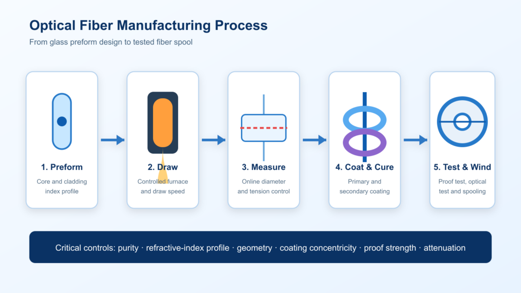
Optical fiber is made by first creating a high-purity glass preform whose core and cladding already contain the required refractive-index profile. The preform is then heated in a draw tower and pulled into a thin, continuous fiber. Diameter is controlled in real time, protective coatings are applied and cured, and the finished fiber is tested for geometry, optical performance and mechanical reliability.
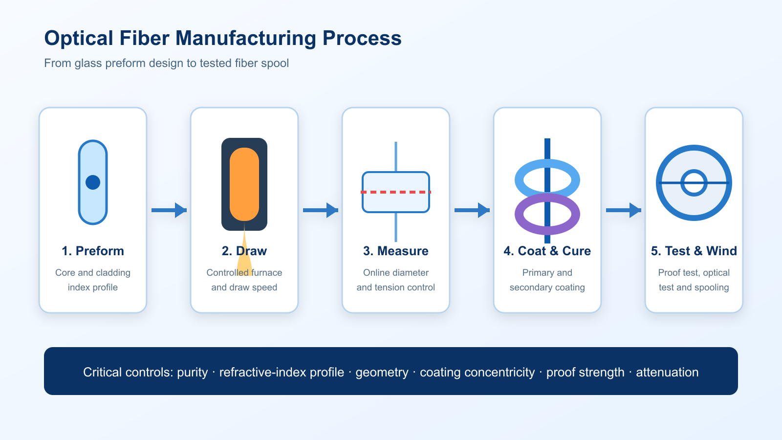
That short explanation answers the basic question, but it does not explain why two fibers with the same nominal diameter can perform very differently. The decisive work happens before and during the draw: material purity, dopant distribution, core geometry, preform quality, draw stability, coating and inspection all influence the final result.
This guide explains the complete optical fiber manufacturing process for engineers and B2B buyers, from the glass preform to the tested fiber spool. It also shows which specifications should be included in an RFQ when standard catalog fiber is not enough.
What Is an Optical Fiber Preform?

An optical fiber preform is a cylindrical glass structure from which optical fiber is drawn. Its cross-section is a scaled-up version of the final fiber: the central core and surrounding cladding are already arranged to create the required refractive-index profile.
The core must have a higher effective refractive index than the cladding for conventional total-internal-reflection guidance. Manufacturers obtain the required index profile by controlling glass composition and dopants. Germanium is commonly associated with raising the refractive index of silica, while fluorine or boron can be used to lower it for particular structures. The right composition depends on wavelength, numerical aperture, mode behavior, attenuation and environmental requirements.
A preform is therefore not simply a large glass rod. It is the optical design translated into manufacturable material. Errors in core concentricity, diameter ratio, dopant uniformity, bubbles, inclusions or contamination can be reproduced over a long length of drawn fiber.
Optical Fiber Manufacturing Process at a Glance
- Define the optical design: target wavelength, mode field or core size, numerical aperture, attenuation, proof-test and coating requirements.
- Form the preform: deposit or assemble high-purity glass to create the required core, cladding and refractive-index profile.
- Consolidate and prepare: convert porous material into transparent glass where applicable, remove moisture and impurities, and prepare the preform for drawing.
- Draw the fiber: heat the preform tip and pull it into a controlled glass filament.
- Apply and cure coating: protect the freshly drawn glass surface immediately after diameter measurement.
- Proof-test and inspect: verify mechanical integrity, geometry and optical performance before release.
Corning describes the industrial OVD sequence as laydown, consolidation and draw, while an ITU technical handbook likewise describes controlled preform feeding, furnace heating, online diameter monitoring, coating and proof testing. These independent descriptions illustrate the same essential principle: the preform creates the optical structure, and the draw process reduces it while preserving that structure.
Step 1: Translate the Application into a Fiber Design
Manufacturing should start with the application, not with a generic material request. A communication link, fiber laser, interferometric sensor, high-power delivery system and nonlinear experiment can require very different core sizes, index profiles and coatings.
Before selecting a preform or fiber, define at least:
- operating wavelength or wavelength range;
- single-mode, few-mode or multimode behavior;
- core diameter, cladding diameter and acceptable tolerances;
- numerical aperture or mode-field-diameter target;
- attenuation and bandwidth requirements;
- polarization, nonlinear or high-power requirements;
- coating material, diameter and operating temperature;
- proof-test level, delivery length and documentation needs.
For unusual geometry or composition, a custom preform may be more appropriate than modifying a standard fiber after drawing. Examples include boron-doped preforms, large-core-diameter preforms and structures that use a fluorine-doped quartz tube.
Step 2: Manufacture the Glass Preform
Several vapor-deposition and assembly methods are used across the optical-fiber industry. The method affects achievable size, index-profile control, production scale and suitability for a particular fiber design. The following comparison is a technology overview; it should not be read as a claim that every supplier or every product uses every method.
| Method | Basic approach | Typical strengths | Selection considerations |
|---|---|---|---|
| MCVD Modified Chemical Vapor Deposition | Glass layers are deposited inside a rotating silica tube and consolidated; the tube is then collapsed into a solid preform. | Flexible layer and dopant control; widely used for communication and specialty-fiber designs. | Inside diameter, deposition recipe, collapse control and final geometry influence scalability and consistency. |
| OVD Outside Vapor Deposition | Fine silica particles are deposited externally on a rotating target to form a porous soot body, which is consolidated into transparent glass. | Scalable preform formation and controlled radial composition. | Laydown uniformity, dehydration and consolidation are critical to purity and geometry. |
| VAD Vapor Axial Deposition | Soot is deposited axially so the preform grows lengthwise before consolidation. | Continuous axial growth and suitability for large preforms. | Stable deposition, profile control and consolidation conditions are essential. |
| PCVD Plasma Chemical Vapor Deposition | Microwave plasma promotes deposition of thin glass layers inside a substrate tube. | Fine control of multi-layer refractive-index profiles. | Equipment, recipe repeatability and tube geometry affect practical production. |
| Stack-and-draw / rod-in-tube | Rods, tubes or capillaries are assembled into a larger structure and fused or drawn. | Useful for microstructured, photonic-crystal, multicore and other non-standard geometries. | Element placement, interface cleanliness, pressure control and draw deformation must be managed. |
For a B2B project, the most important question is not “Which acronym is best?” It is “Which process can repeatedly deliver the target optical profile, geometry, volume and documentation?” A method that is ideal for a large-volume communication fiber may not be the best route for a small batch of specialty fiber.
Step 3: Consolidation, Dehydration and Preform Preparation
When the deposition process creates porous soot, it must be consolidated into dense, transparent glass. Moisture and residual contaminants must be controlled because hydroxyl-related absorption and other impurities can increase optical loss at relevant wavelengths.
The prepared preform is also inspected for visible defects, dimensional consistency and profile conformity. Depending on the design, it may be sleeved, overclad, stretched, collapsed, machined or cleaned before drawing. For structured preforms, the arrangement must remain stable enough to survive heating and dimensional reduction.
Useful pre-draw inspection items include:
- outside diameter, usable length and straightness;
- core diameter and core-to-cladding ratio;
- core/cladding concentricity;
- refractive-index profile or related design data;
- bubbles, inclusions, cracks, interface defects and contamination;
- surface condition and end preparation;
- traceability of material and production lot.
Step 4: Draw the Preform into Optical Fiber
In the draw tower, the preform is fed into a high-temperature furnace. The softened tip forms a narrow strand that is pulled downward. A closed-loop control system coordinates furnace conditions, preform feed and draw speed so the fiber reaches the target diameter.
Industrial silica drawing commonly uses temperatures around 2,000 °C. An ITU handbook describes optical monitoring of diameter during drawing and explains that a polymer coating is applied during the same manufacturing stage to protect the fiber surface and preserve transmission performance.
The optical structure scales down with the glass. For example, if the preform’s core-to-cladding ratio is correct and the structure does not deform during heating, the drawn fiber can retain the intended proportional geometry. However, hole collapse, asymmetric softening, viscosity mismatch or unstable tension can alter non-standard designs. This is why draw parameters are part of product engineering, not merely production settings.
Step 5: Apply the Protective Coating
Freshly drawn glass is vulnerable to surface damage. The fiber therefore passes through coating applicators soon after diameter measurement. The liquid coating is centered around the glass and then cured, commonly by ultraviolet energy.
Coating selection depends on handling and service conditions. Standard acrylate systems are common for telecommunications, while specialty applications may require high-temperature, low-index, hermetic or other coating systems. Important coating parameters include:
- coating material and cure condition;
- coated diameter and tolerance;
- coating-cladding concentricity;
- strip force and compatibility with termination processes;
- temperature, chemical, humidity and radiation exposure;
- microbend sensitivity and mechanical handling.
Step 6: Proof-Test and Verify the Finished Fiber
Finished fiber is not qualified by diameter alone. Testing should reflect both the fiber design and the buyer’s end use. Typical categories are:
| Category | Example parameters | Why the buyer should care |
|---|---|---|
| Geometry | Cladding diameter, core diameter, non-circularity, concentricity, coating diameter | Affects splicing, coupling, connectorization and repeatability. |
| Optical | Attenuation, numerical aperture, mode-field diameter, cutoff wavelength, bandwidth or spectral transmission | Determines whether the fiber meets system loss, mode and signal requirements. |
| Mechanical | Proof test, tensile behavior, coating integrity, bend performance | Reduces the risk of handling failures and premature breaks. |
| Specialty | Polarization extinction ratio, beat length, nonlinear coefficient, photosensitivity, radiation response or high-power handling | Confirms performance that is specific to the application rather than generic fiber geometry. |
| Documentation | Lot traceability, test report, inspection record, spool length and labeling | Supports incoming inspection, qualification and regulated procurement workflows. |
Proof testing is used to screen mechanically weak sections, but it does not replace optical or geometric inspection. The appropriate acceptance plan should be agreed before production, especially for custom fiber or preforms.
How Preform Parameters Influence Final Fiber Performance
| Preform parameter | Potential effect in the drawn fiber |
|---|---|
| Core/cladding ratio | Helps determine final core size and modal behavior. |
| Refractive-index profile | Influences numerical aperture, mode-field behavior, dispersion and bandwidth. |
| Dopant concentration and uniformity | Affects index contrast, absorption, gain, photosensitivity or thermal behavior, depending on the dopant. |
| Core concentricity | Influences coupling, splicing and alignment repeatability. |
| Purity and hydroxyl content | Can affect attenuation and absorption bands. |
| Bubbles, inclusions and interfaces | May create scattering, local weakness or draw instability. |
| Preform size and usable length | Influences obtainable fiber length, production economics and lot planning. |
How to Specify Optical Fiber or a Preform for an RFQ
A strong RFQ reduces technical clarification cycles and prevents a nominally similar but unsuitable material from being quoted. Send the target values you know and mark genuinely flexible parameters as such.
- Application: communication, laser delivery, sensing, amplifier, interferometry, nonlinear optics or another use.
- Operating wavelength: center wavelength and required range.
- Fiber type: single-mode, multimode, polarization-maintaining, doped, microstructured or custom.
- Geometry: core, cladding and coating diameters; shape; concentricity; tolerances.
- Optical targets: attenuation, NA, MFD, cutoff, bandwidth, PER or other application-specific values.
- Material and coating: silica composition, dopants, coating system and operating environment.
- Mechanical requirements: proof test, bend radius, tensile or environmental expectations.
- Quantity: preform count or fiber length, required spool lengths and forecast volume.
- Inspection documents: certificate, measured data, traceability and labeling format.
- Drawing or specification: attach any controlled drawing, test method or approved reference sample.
If some values are unknown, provide the application, wavelength, launch conditions and system constraints. Opticlumos can review available preform, communication fiber and specialty-fiber routes against the stated requirements.
Frequently Asked Questions
How is optical fiber made?
Optical fiber is made by creating a glass preform with the required core, cladding and refractive-index profile, heating the preform in a draw tower, pulling it to the target glass diameter, applying and curing a protective coating, and testing the finished fiber.
What is the difference between a preform and optical fiber?
A preform is the much larger glass structure that contains the optical design. Optical fiber is the thin, continuous product drawn from that preform. Their cross-sections are related, but the draw process reduces the dimensions dramatically.
What materials are used to make optical fiber?
High-purity silica is the most common base material for telecommunications and many specialty fibers. Controlled dopants modify refractive index or add functions such as optical gain, photosensitivity or other application-specific behavior. Some specialty fibers use non-silica glasses.
What do MCVD, OVD, VAD and PCVD mean?
They are different vapor-deposition routes for producing optical-fiber preforms: Modified Chemical Vapor Deposition, Outside Vapor Deposition, Vapor Axial Deposition and Plasma Chemical Vapor Deposition. Each has different process characteristics, and the best choice depends on the target fiber, scale and profile-control requirements.
Why is coating applied immediately after drawing?
The coating protects the newly drawn glass surface from damage and environmental exposure. It also supports handling and helps preserve mechanical reliability and optical performance.
Which parameters should a buyer check first?
Start with wavelength, fiber type, core/cladding geometry, numerical aperture or mode-field diameter, attenuation, coating, proof-test level, delivery length and required documentation. Specialty applications should add parameters such as PER, beat length, nonlinear response or environmental limits.
Conclusion
The optical fiber manufacturing process is a connected chain: application requirements define the optical design; the preform establishes the material and refractive-index structure; drawing controls final geometry; coating protects the glass; and testing verifies that the product is fit for use. Buyers get better results when these steps are treated as one engineering system rather than separate catalog choices.
Planning a preform or fiber project? Send Opticlumos your wavelength, dimensions, performance targets, expected quantity and any drawing or specification file. Our technical team will review the requirements and recommend a suitable product or customization path.