
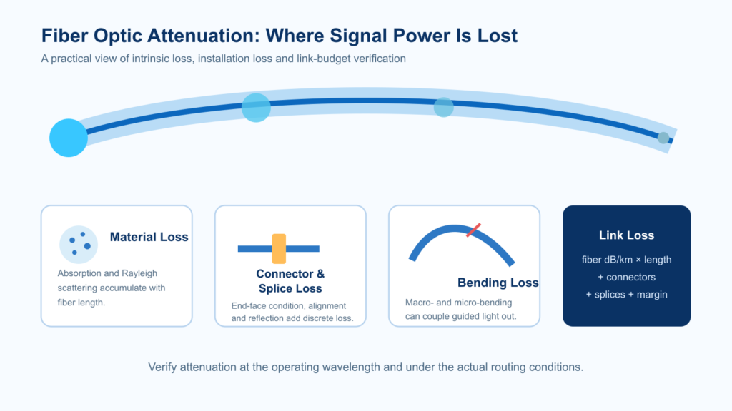
Fiber optic attenuation is the reduction of optical power as light travels through a fiber or passes through connectors, splices, bends and other components. It is expressed in decibels (dB), while the attenuation coefficient of the fiber itself is normally expressed in dB per kilometer (dB/km). Lower attenuation supports longer transmission distance and a larger system power margin—but the correct limit always depends on fiber type, operating wavelength, link length and application.
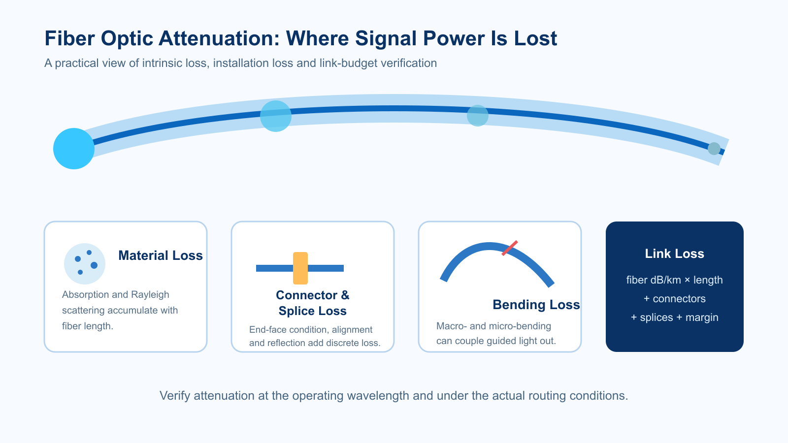
For a buyer or system engineer, the practical question is not simply “Which fiber has the lowest loss?” It is: What attenuation is acceptable at the actual operating wavelength, after cabling and installation, with enough margin for connectors, splices, aging and measurement uncertainty?
Quick answer
For common G.652.D single-mode cable, ITU-T G.652 specifies a maximum attenuation coefficient of 0.40 dB/km across 1310–1625 nm and 0.30 dB/km in the 1530–1565 nm region. Installed-link loss will be higher because connectors, splices and bends add loss. Specialty fibers must be evaluated against their own design wavelength and application—not generic telecom limits.
What Is Fiber Optic Attenuation?
Attenuation describes how much optical power is lost between two points. If a signal enters a fiber at power Pin and exits at Pout, total attenuation is:
Loss (dB) = 10 log10(Pin / Pout)
When the measured loss is divided by fiber length L in kilometers, the attenuation coefficient is:
Attenuation coefficient α (dB/km) = Loss (dB) / L (km)
A 3 dB loss means that approximately half of the optical power remains. A 10 dB loss means approximately one tenth remains. Because dB is logarithmic, losses from separate link elements can be added directly.
Attenuation vs. Insertion Loss: Do Not Confuse Them
| Term | What it describes | Typical unit | Common use |
|---|---|---|---|
| Fiber attenuation coefficient | Distributed loss within a specified length of fiber | dB/km | Fiber datasheets, production testing and wavelength comparison |
| Insertion loss | Total power reduction caused by inserting a component or complete link | dB | Connectors, splitters, patch cords and installed links |
| Return loss | Ratio related to reflected optical power | dB | Connector quality, reflections and high-performance links |
| Optical loss budget | Maximum loss the transmitter–receiver system can tolerate | dB | Network design and acceptance planning |
A fiber can meet its dB/km specification while an assembled link still fails because of contaminated connectors, poor splices, excessive bending or too little engineering margin. Procurement specifications should therefore separate fiber attenuation from finished-link insertion loss.
What Causes Attenuation in Optical Fiber?
1. Rayleigh scattering
Microscopic density and composition variations in silica scatter a small portion of the guided light. Rayleigh scattering is a fundamental loss mechanism in conventional silica fiber and becomes much stronger at shorter wavelengths. This is one reason silica single-mode systems generally show lower intrinsic attenuation near 1550 nm than near 1310 nm.
2. Material absorption
Some optical energy is absorbed by the glass and converted to heat. Intrinsic absorption is associated with the silica material itself, while extrinsic absorption can come from impurities. Hydroxyl (OH) content is particularly important because it can create absorption peaks in the spectrum. Low-water-peak fiber is designed to support broader wavelength use around the traditional water-peak region.
3. Macrobending and microbending
A visible, large-scale bend with too small a radius can allow guided light to escape from the core. Microbending consists of small local distortions caused by cabling pressure, installation stress, temperature change or uneven contact. Bend loss is wavelength-dependent and often becomes more pronounced at longer wavelengths.
4. Waveguide and geometry effects
Core profile, mode-field diameter, numerical aperture, concentricity and microstructure influence how tightly light is confined. These parameters are particularly important for polarization-maintaining photonic crystal fiber, high-nonlinearity PCF and other specialty designs, where a generic telecom attenuation target may be technically inappropriate.
5. Connections, splices and contamination
Connectors and splices are discrete loss events rather than part of the fiber’s intrinsic dB/km value. Core offset, angular misalignment, incompatible mode-field diameters, poor end-face geometry, air gaps and contamination can all add insertion loss. In short links, these events can contribute more loss than the fiber length itself.
Typical Fiber Attenuation by Wavelength
The values below are planning references, not universal acceptance limits. The applicable product datasheet, contract specification and test method must control the final decision.
| Fiber / application | Common test wavelength | Planning or standards reference | Important note |
|---|---|---|---|
| G.652.D single-mode cable | 1310 nm | Maximum 0.40 dB/km under ITU-T G.652 | 1310 nm is near the zero-dispersion region for G.652 fiber |
| G.652.D single-mode cable | 1550 nm | Maximum 0.30 dB/km across 1530–1565 nm under ITU-T G.652 | Often selected for lower attenuation and longer reach |
| 50/125 μm multimode | 850 nm | 3.5 dB/km is a conservative TIA-based loss-budget value | Check OM grade, source type and bandwidth requirement |
| 50/125 μm multimode | 1300 nm | 1.5 dB/km is a conservative TIA-based loss-budget value | System optics and modal bandwidth still govern reach |
| Specialty, PM, PCF or large-core fiber | Application-specific | Use supplier data at the specified wavelength | Geometry, coating, bend condition and launch can dominate the result |
The current ITU-T G.652 recommendation also notes that values specified for cabled factory lengths should not automatically be applied to short indoor cables, drop cables or jumpers. A short assembly may have a high calculated dB/km figure even when its absolute insertion loss is acceptable, because connector loss dominates and the length is small.
Why Does 1550 nm Usually Have Lower Loss Than 1310 nm?
As wavelength increases, Rayleigh scattering decreases sharply. Around 1550 nm, silica fiber reaches a low-loss transmission window before infrared absorption and bend sensitivity become increasingly important. Around 1310 nm, attenuation is somewhat higher, but standard G.652 fiber has near-zero chromatic dispersion, which can simplify certain links.
Therefore, “lower attenuation” does not automatically mean “better system performance.” Wavelength selection must also consider dispersion, transceiver availability, detector response, nonlinear effects, bend performance and the link architecture. For a broader explanation of how the glass structure is created, see how optical fiber is made from preform to finished fiber.
How to Calculate a Fiber Optic Loss Budget
A practical link estimate adds the planned loss of every element:
Total estimated loss = (fiber length × dB/km) + connector loss + splice loss + passive-component loss + engineering margin
Example
Consider a 20 km single-mode link operating at 1550 nm with an assumed fiber attenuation of 0.25 dB/km, two connector pairs at 0.5 dB each, eight fusion splices at 0.1 dB each and a 3 dB engineering margin:
- Fiber: 20 km × 0.25 dB/km = 5.0 dB
- Connectors: 2 × 0.5 dB = 1.0 dB
- Splices: 8 × 0.1 dB = 0.8 dB
- Engineering margin: 3.0 dB
- Total design allowance: 9.8 dB
The transmitter output and receiver sensitivity must provide a usable system power budget greater than this value. The final margin should reflect aging, repairs, temperature, future patching and measurement uncertainty—not only initial laboratory performance.
How Fiber Attenuation Is Measured
Cutback measurement
Cutback testing compares transmitted power through a long specimen with power through the same fiber after it is cut back to a short reference length, while maintaining the launch condition. It is a reference method for characterizing the distributed attenuation of fiber because it removes much of the uncertainty from connector coupling. Its destructive nature makes it more suitable for manufacturing or laboratory qualification than for installed links.
Optical loss test set (OLTS)
A calibrated light source and power meter measure end-to-end insertion loss at one or more wavelengths. This is the preferred method for proving whether an installed link meets its total loss budget. Reference-cord quality, connector cleaning, launch conditions and the chosen one-, two- or three-cord reference procedure materially affect the result.
Optical time-domain reflectometer (OTDR)
An OTDR analyzes backscattered and reflected light as a function of distance. It can estimate fiber attenuation and identify the location of bends, splices, connectors and breaks. It is invaluable for diagnostics, but it does not replace end-to-end insertion-loss testing. Bidirectional OTDR testing can reduce errors caused by differences in backscatter between joined fibers.
Spectral attenuation measurement
For CWDM, DWDM, wideband components and specialty fibers, a single test wavelength may be insufficient. A broadband source with an optical spectrum analyzer, a tunable source with a broadband power meter, or a multi-wavelength OTDR can characterize the attenuation profile across the operating band.
How to Reduce Unexpected Fiber Loss
- Specify the wavelength. A dB/km value without a test wavelength is incomplete.
- Control bend radius. Include both installed and long-term bend conditions, especially at 1550 and 1625 nm.
- Match fiber geometry. Mode-field mismatch, core offset and numerical-aperture mismatch can increase splice or coupling loss.
- Inspect and clean every connector. Contamination is a common cause of avoidable link loss and reflectance.
- Use the correct launch condition. Multimode and specialty-fiber measurements are especially sensitive to how modes are excited.
- Measure at relevant temperatures. Coatings, cabling pressure and microbending can change under environmental stress.
- Keep test records. Record wavelength, method, reference procedure, equipment, direction, temperature and sample length.
Procurement Checklist: What to Put in an RFQ
For communication optical fiber or a custom specialty-fiber project, include the following information:
- fiber type or applicable standard, such as G.652.D, multimode, PM or PCF;
- operating and test wavelength(s);
- maximum attenuation coefficient in dB/km and whether it applies to bare fiber, cabled fiber or a finished assembly;
- required length, delivery format and allowable continuous-length tolerance;
- core, cladding, coating and mode-field requirements;
- minimum bend radius and environmental conditions;
- connector, splice or termination requirements;
- required test method, direction, sampling level and report format;
- dispersion, bandwidth, polarization or nonlinear parameters relevant to the application;
- prototype quantity, annual volume and target schedule.
If the project begins at the material stage, Opticlumos also supports selection across optical fiber preforms and finished fiber categories. Review the product portfolio or send your wavelength, geometry and application requirements for technical review.
Frequently Asked Questions
What is a good dB loss for fiber optics?
There is no universal “good” value. For long G.652.D cable, 0.40 dB/km at 1310 nm and 0.30 dB/km at 1550 nm are useful maximum reference values from ITU-T G.652. A finished link must also account for connectors, splices, bends, passive components and design margin.
What is acceptable dB loss for a fiber link?
Acceptable link loss is the lower of the project’s specified acceptance limit and the available transmitter-to-receiver power budget after margin. Calculate the expected loss before installation, then verify the completed link with an optical loss test set.
Is attenuation the same as signal loss?
Attenuation is a form of signal loss, but engineers often use it specifically for distributed reduction along fiber, expressed in dB/km. “Link loss” or “insertion loss” normally includes fiber, connectors, splices and other components and is expressed in dB.
Can an OTDR measure fiber attenuation?
Yes. An OTDR can estimate attenuation from the slope of backscatter and locate individual loss events. For end-to-end acceptance, a calibrated light source and power meter provide the direct insertion-loss measurement; OTDR results complement that test by showing where loss occurs.
Why can loss increase after cabling?
Cabling can introduce microbending, macrobending, residual stress and temperature-dependent pressure. That is why bare-fiber attenuation and cabled-fiber attenuation should be specified separately when the application is sensitive.
Do specialty fibers use the same attenuation limits as telecom fiber?
No. Specialty fibers may optimize polarization, nonlinearity, mode area, wavelength range, power handling or sensing response rather than minimum telecom-band loss. Acceptance criteria should be defined at the actual operating wavelength and under representative launch, bend and packaging conditions.
Technical References
- ITU-T G.652 (08/2024): Characteristics of a single-mode optical fibre and cable
- ITU-T G.650.1 (01/2024): Definitions and test methods for single-mode fibre and cable
- NECA/FOA 301: Installing and Testing Fiber Optics
- VIAVI Reference Guide to Fiber Optic Testing, Volume 2
Note: Published limits and planning values must be interpreted together with the applicable fiber category, cable construction, specimen length, wavelength and test method. For a purchase specification, use the agreed product datasheet and contract requirements.