
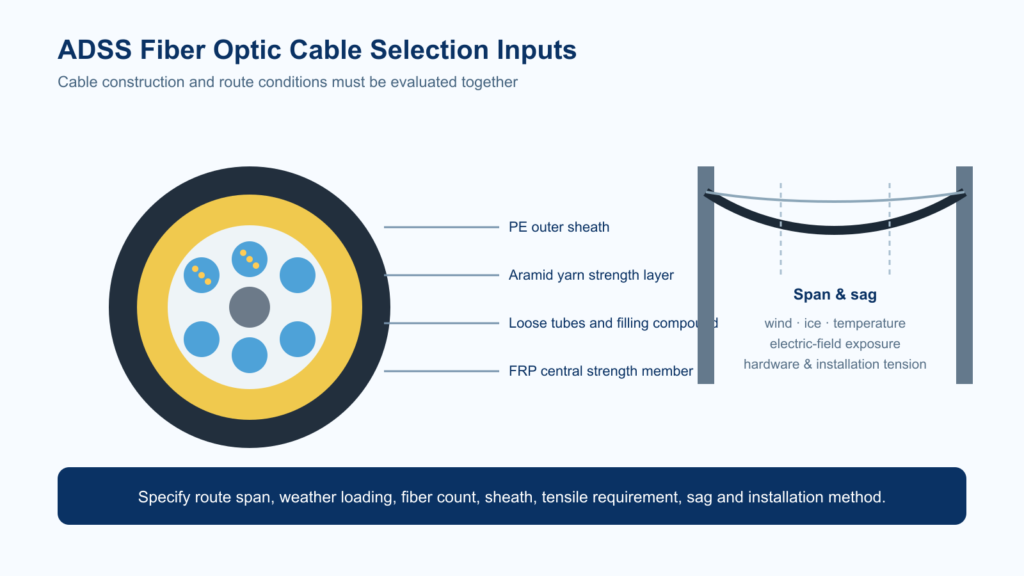
ADSS fiber optic cable is an all-dielectric, self-supporting aerial cable used where optical fiber must cross poles or utility corridors without a separate messenger wire. Correct selection depends on span, environmental loading, electrical-field exposure, fiber count and installation tension—not fiber count alone.
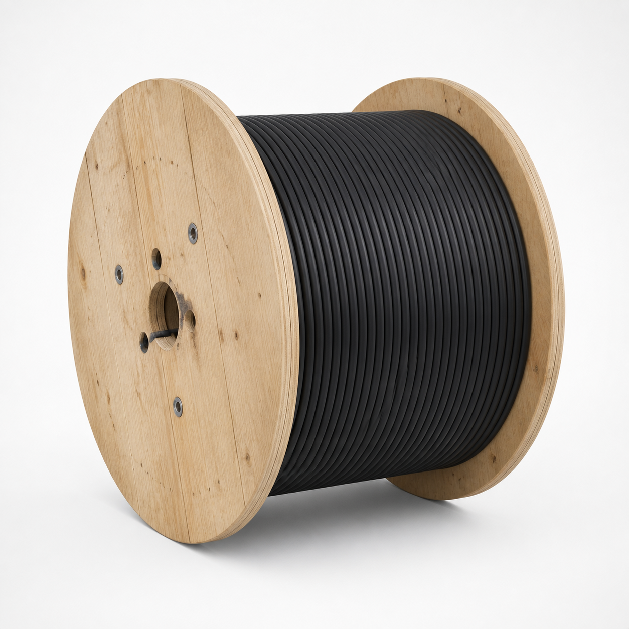
What Does ADSS Cable Mean?
ADSS means all-dielectric self-supporting. “All-dielectric” means the cable contains no metallic strength member or armor. “Self-supporting” means its dielectric strength system carries the cable between support points without a steel messenger.
This construction gives network designers a practical aerial option for telecom backbones, substations, railway communications, campus links and utility rights-of-way. It can also reduce electrical bonding and grounding concerns associated with metallic aerial cables, although safe route design and utility installation procedures are still essential.
Typical ADSS Fiber Optic Cable Structure
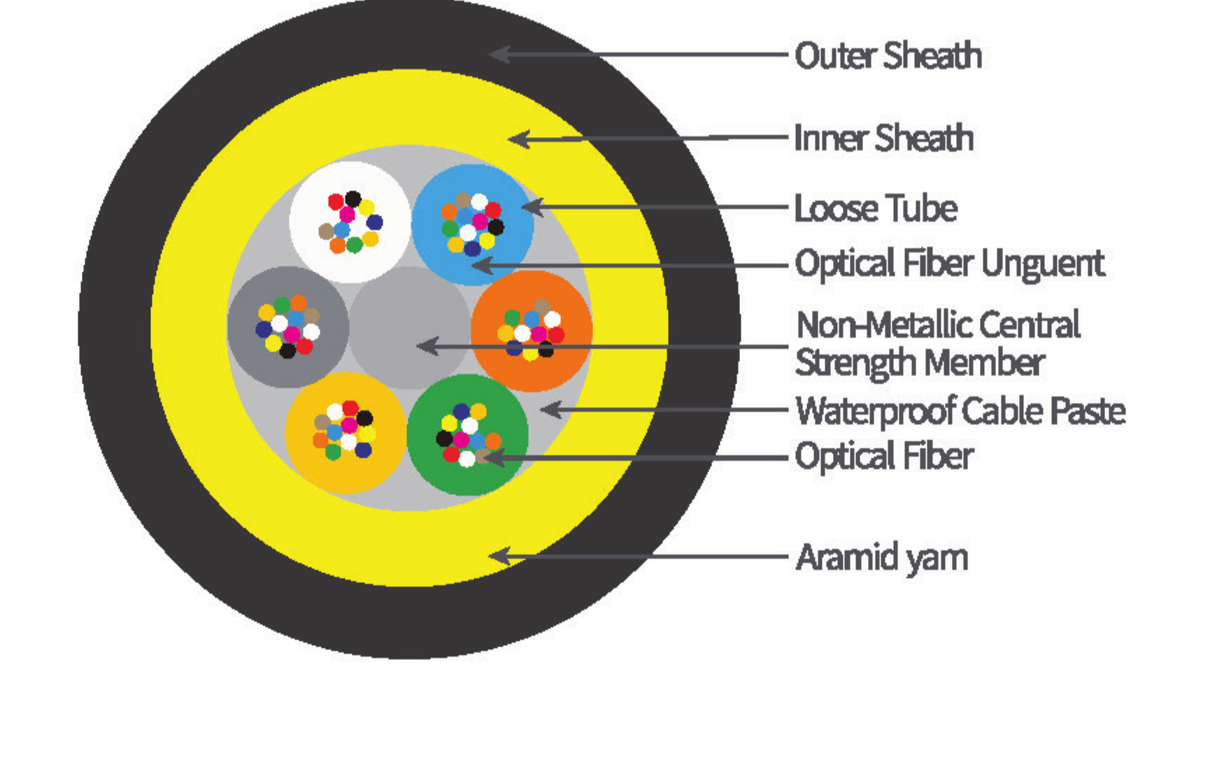
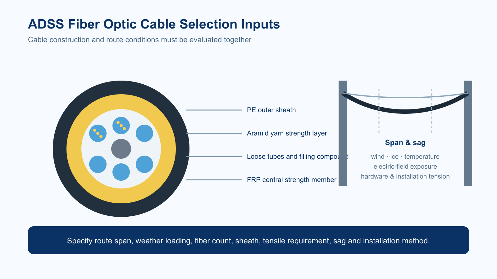
Designs vary by span and environment, but a typical loose-tube ADSS cable contains:
- Optical fibers: commonly single-mode G.652.D; bend-insensitive or non-zero-dispersion-shifted fibers may be specified for particular networks.
- Gel-filled or dry water-blocked loose tubes: protect fibers from moisture and isolate them from tensile strain.
- Central strength member and fillers: maintain the cable geometry.
- Water-blocking elements: limit longitudinal moisture migration.
- Aramid yarn: provides dielectric tensile strength for self-supporting spans.
- Inner and outer sheath: protect the cable from abrasion, sunlight, moisture and environmental loading. Double-sheath designs provide additional mechanical protection.
For project-specific structure drawings and reference configurations, see the Opticlumos ADSS fiber optic cable product page.
How to Select ADSS Cable by Span and Loading
Span is the distance between support points, but it is only the starting input. Cable tension is also affected by sag, wind pressure, ice accumulation, temperature, cable diameter, terrain and installation method. The correct design should be checked against the route’s loading case rather than selected from a generic “maximum span” label.
| Design input | Why it matters | Information to provide |
|---|---|---|
| Span and sag | Determine tensile load and clearance | Nominal span, maximum span, allowable sag and pole height |
| Wind and ice | Increase radial and longitudinal loading | Local design wind speed, ice thickness and governing code |
| Temperature range | Changes cable length, sag and material performance | Installation and operating temperature limits |
| Electrical environment | Influences sheath selection and tracking risk | Line voltage, cable position and calculated space potential |
| Hardware | Controls stress transfer at support points | Suspension/dead-end arrangement, pole type and fitting requirements |
| Fiber plan | Sets capacity and cable geometry | Fiber count, fiber standard, tube allocation and spare capacity |
Opticlumos offers reference ADSS configurations from 24 to 144 fibers for approximately 50–500 m spans. These are configuration ranges, not a substitute for route-specific engineering review.
PE Sheath vs. Tracking-Resistant Sheath
A polyethylene (PE) outer sheath is widely used for ordinary aerial environments. Near high-voltage conductors, dry-band arcing and electrical tracking can become design concerns. A tracking-resistant sheath may be specified after the electrical field at the proposed cable position is assessed.
Do not choose the sheath only from nominal line voltage. Phase geometry, attachment position, pollution, humidity and grounding arrangement can change the electrical stress experienced by the cable.
Single-Sheath vs. Double-Sheath ADSS
| Configuration | Typical benefit | Selection note |
|---|---|---|
| Single sheath | Lower diameter and weight | Often suitable for lighter loading and shorter or moderate spans |
| Double sheath | Additional mechanical and environmental protection | Consider for higher loading, longer spans or demanding utility routes |
The final choice should be verified using tensile, crush, impact, temperature-cycle, water-penetration and sheath-performance requirements for the project.
ADSS vs. OPGW vs. Figure-8 Cable
| Cable type | Support method | Metallic content | Common use |
|---|---|---|---|
| ADSS | Self-supporting dielectric strength members | No metallic components in the cable | New or retrofit aerial fiber routes, including utility corridors |
| OPGW | Installed as an overhead ground wire | Metallic | Power-line grounding plus optical communications |
| Figure-8 | Integrated messenger supports the optical unit | May use a metallic or dielectric messenger | Telecom distribution routes where messenger construction is preferred |
ADSS Cable Installation Checklist
- Survey every span, angle, clearance and road or river crossing.
- Confirm the cable design and hardware against the maximum loading case.
- Use compatible dead-end, suspension, vibration-control and protective fittings.
- Control pulling tension and observe the specified minimum bend radius.
- Prevent the cable from contacting the ground, sharp edges or rotating hardware during payout.
- Follow electrical utility safe-working distances and approved line procedures.
- Record reel identity and perform pre-installation and post-installation optical tests.
Standards and Test Documentation
IEC 60794-4-20 is the IEC family specification for self-supporting aerial telecommunication cables used along electrical power lines. It covers construction, optical and mechanical performance, installation guidelines and test requirements. IEEE 1222-2019 is another commonly referenced ADSS specification for electric utility lines.
For procurement, request a datasheet and applicable test records that match the offered configuration—not only a generic family brochure.
Information to Include in an ADSS RFQ
- Route length, nominal span and maximum span
- Wind, ice and temperature design conditions
- Power-line voltage and proposed cable position, if applicable
- Fiber count, fiber type and color-code requirement
- Single or double sheath and PE or tracking-resistant requirement
- Required standards, tests, drum length and delivery destination
- Suspension, dead-end and vibration-control hardware requirements
Frequently Asked Questions
What is ADSS fiber optic cable used for?
ADSS is used for self-supporting aerial optical links on telecom poles, utility rights-of-way, substations, railways, campuses and other routes where a separate messenger wire is not desired.
Does ADSS cable contain metal?
No. A true ADSS cable is all-dielectric and uses non-metallic strength members such as aramid yarn.
How far can ADSS cable span?
Available spans range from short distribution routes to several hundred metres, but the permitted span depends on sag, wind, ice, temperature, cable construction and hardware. Opticlumos reference designs cover approximately 50–500 m and require project review.
Can ADSS cable be installed on high-voltage power lines?
Yes, when the route, cable position, electrical field, sheath material, hardware and installation procedure are engineered for the line. A tracking-resistant sheath may be required in higher-stress locations.
What information is needed for an ADSS quotation?
Provide span and loading data, fiber count/type, line voltage and cable position where relevant, sheath requirement, standards, hardware, drum length and destination.
Request an ADSS Cable Engineering Review
Send your route span table, environmental loading, fiber count and installation requirements. Opticlumos will review a suitable cable construction, sheath and hardware basis for quotation.
Technical references: IEC 60794-4-20; IEEE 1222-2019. Project specifications and local safety rules take precedence over this general selection guide.