
A 100GBASE-SR4 link needs a correctly mapped parallel multimode channel and enough optical margin on every active lane. Check both before ordering the MPO assemblies.
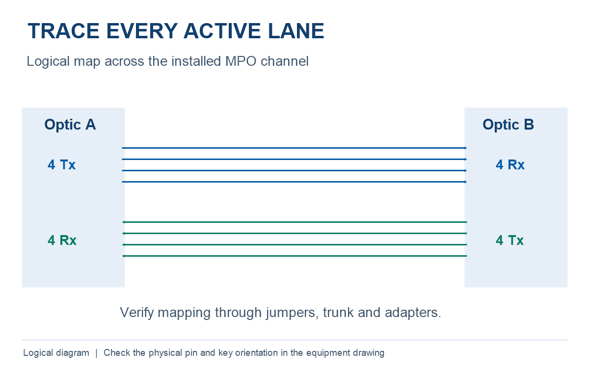
Identify both transceiver models and the supported fiber grade and reach. Trace the four transmit and four receive lanes across the installed MPO channel. Add fiber, mated-pair and passive losses for each lane at the specified wavelength and reference planes, then compare the worst lane plus the chosen reserve with the applicable channel limit.
Check the 100G optic before choosing MPO cabling
Read the connector, fiber, reach and channel limit for each part number. A Cisco QSFP-100G-SR4-S is one example of an 850 nm parallel multimode optic specified for up to 70 m on OM3 and 100 m on OM4, with an MPO interface. The vendor specifies PC or UPC patch-cord connections for that model. Verify both endpoints and the full channel against the current product documentation. Cisco 100GBASE QSFP module data sheet.
| Check | What to record | Why it affects the order |
|---|---|---|
| Transceivers | Part number and interface at each end | 100G modules can use different connectors, fiber grades and lane arrangements. |
| Optical channel | OM grade, installed length, applicable loss limit and wavelength | Modal bandwidth and insertion loss each affect compliance. |
| MPO interfaces | Ferrule population, guide-pin state, key orientation and polish at each mating point | These details govern physical assembly and fiber alignment. |
| Polarity | End-to-end transmit-to-receive map | The entire chain determines the lane map through trunks, patch leads and adapters. |
Verify the installed MPO lane map
Assign connector end references in the drawing and mark the viewing direction. Map the transmit lanes at end A to the matching receive lanes at end B, then trace the reverse direction. Include every trunk, conversion module, adapter and patch lead. Type A, B or C labels refer to components or specified methods. Confirm the resulting map using the full path and the equipment pinout.
Calculate an 80 m OM4 link loss budget
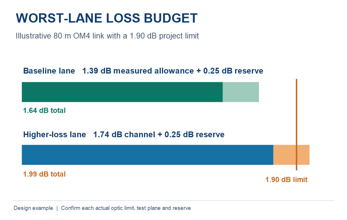
For a planning example, assume a 1.90 dB project channel limit, a 0.25 dB engineering reserve, and 80 m of OM4 at a design attenuation of 3.0 dB/km. Use three mated pairs at 0.35 dB each and 0.10 dB for a separately budgeted splice. These are worksheet assumptions. Obtain actual project values and follow the published limits of the selected optics.
| Budget item | Example calculation | Loss |
|---|---|---|
| Fiber | 0.080 km × 3.0 dB/km | 0.24 dB |
| Three mated pairs | 3 × 0.35 dB | 1.05 dB |
| Splice | One separate allowance | 0.10 dB |
| Planned channel loss | 0.24 + 1.05 + 0.10 | 1.39 dB |
| Planned loss with reserve | 1.39 + 0.25 | 1.64 dB |
| Margin to project limit | 1.90 − 1.64 | 0.26 dB |
If one mated pair contributes 0.70 dB on a particular lane, that lane rises to 1.74 dB. With the reserve it requires 1.99 dB and misses the project design target by 0.09 dB. Inspect, clean or remediate the affected path and retest. Count each interface once and align the worksheet with the field test reference planes.
For help separating fiber attenuation from connection and splice losses, see the fiber optic attenuation guide.
Accept an SR4 channel lane by lane
- Agree the channel endpoints, test wavelength, launch condition, optical-loss test set reference procedure and pass limit.
- Inspect and clean end faces with tools appropriate to the ferrule. Verify pin compatibility and end-to-end polarity before loss testing.
- Save the loss and mapping result for each active lane. Use the worst lane for channel acceptance and retain any spare-fiber measurements the specification requires.
- Record the test direction, reference method and instrument details so that the results can be checked after installation or rework.
The Fluke Networks guide to testing MPO configurations discusses reference procedures when test leads have different pinning.
Frequently asked questions
Can a 12-position MPO ferrule support an eight-fiber SR4 channel?
Yes, when the eight populated positions match the transceiver pinout, the complete channel maps Tx to Rx, and pinning, keying and polish match the interfaces. Verify the physical layout on both endpoints.
Does an average of the lane losses qualify the link?
Compare each active lane with the applicable channel limit. An average can hide one failing lane.
Can a link within its loss budget exceed the specified reach?
Follow both the specified reach and loss limit. The supported reach also accounts for fiber modal bandwidth and the transceiver characteristics.
Request an MPO link configuration review
Send both optic models, the OM grade and route length, the end-to-end lane map, the MPO pin and key specifications, the loss target, quantities and test-report requirements.