
A PM fiber connector can fit a port and still have the wrong polarization-axis relationship. The useful specification connects three things: the intended launch axis, the connector key at each end, and the finished assembly’s test conditions.
PM fiber slow axis vs fast axis: what changes?
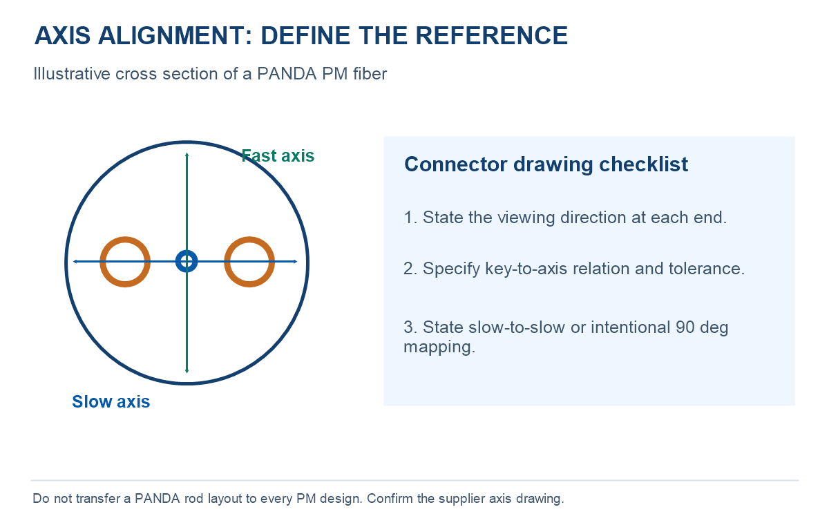
As explained in FiberLabs’ PM fiber technical note, birefringence creates different propagation constants for the two principal axes. In a typical PANDA cross section, the stress-applying rods provide a useful visual reference. Elliptical-core and other PM designs require their own axis identification; do not infer every axis from the same physical feature.
| Question | Slow axis | Fast axis | Specification consequence |
|---|---|---|---|
| Relative phase propagation | Higher effective index; lower phase velocity | Lower effective index; higher phase velocity | These labels do not describe data rate, attenuation or a quality grade. |
| Can it be the launch axis? | Yes, when selected by the optical system | Yes, when selected by the optical system | Follow the source, component and receiver requirements. |
| How is it identified at a connector? | Often referenced to the key | Orthogonal to the slow axis | State the actual key-to-axis relationship and angular tolerance at both ends. |
For a fuller explanation of fiber structures and beat length, use the PM fiber selection guide. This article focuses on the axis reference that must survive launch, termination and mating.
Specify connector keys without an end-view ambiguity
A drawing should label each end A and B, identify whether the viewer looks into the connector face or along the cable, and show the selected axis relative to the key. Two sketches can appear mirrored when their viewing directions differ. Agree a common convention before deciding whether a drawing represents straight axis mapping or an intentional 90-degree relationship.
Thorlabs’ PM FC/PC patch-cable specifications illustrate a stated slow-axis-to-key convention. Treat this as an example of a documented convention, not a universal promise for every PM connector. Mechanical mating, key width, polish and optical-axis alignment each need verification.
- End A: connector family, polish, key geometry, selected axis, view direction and allowed angular deviation.
- End B: the same fields, plus the intended relationship to End A.
- Intermediate devices: coupler, isolator, modulator or splice axis mapping, if present.
- Acceptance: wavelength, launch/reference quality, assembly state, measurement method and agreed PER limit.
APC describes the angled endface polish, not the selected polarization axis. Review UPC vs APC compatibility separately, then use the PM jumper ordering checklist to complete the assembly definition.
How much does an angular launch error matter?
An ideal projection model helps explain sensitivity. For a purely linearly polarized input at an angle θ to the intended axis, the axis powers are proportional to cos²θ and sin²θ. Their ratio in decibels is 10 log10(cos²θ / sin²θ), equivalent to −20 log10(tan θ) for an error between 0 and 45 degrees. The values below are calculated examples, not measured product results.
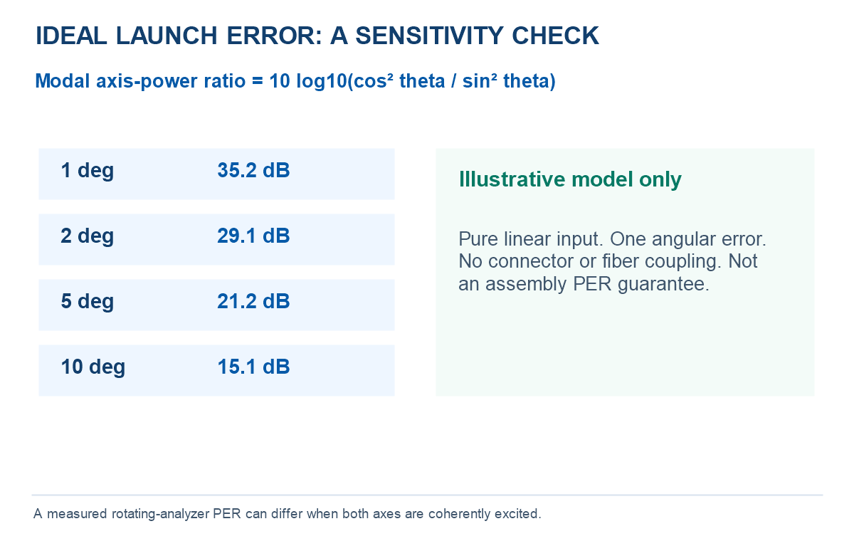
Do not convert this calculation into a guaranteed assembly PER or simply add several angular-error values in dB. With coherent excitation of both axes, the relative phase also affects the output polarization and a rotating-analyzer reading. Thorlabs’ output-extinction-ratio analysis discusses alignment, stress and fiber imperfections. A high reading at one undisturbed instant does not by itself establish robust axis alignment.
A practical alignment and acceptance sequence
- Confirm the launch. Record wavelength, source bandwidth and reference polarization. Identify the intended slow or fast axis from the approved drawing.
- Check the interfaces. Confirm connector keying, polish and axis mapping through every relevant component. Inspect and clean with a compatible procedure before mating.
- Measure the finished path. Use the agreed analyzer method, reference setup and instrument range. Record insertion loss alongside PER; one does not replace the other.
- Check repeatability. Apply only the agreed reconnect, bend and temperature conditions within the component limits. Keep the same reference conventions between measurements.
- Report limitations. State an instrument-limited bound when applicable and distinguish bare-fiber crosstalk from assembly-level acceptance.
Use the copyable PER measurement record for the setup and result fields. If PER changes after handling, inspect launch stability, connector seating, cable stress and analyzer limitations before attributing the result to one component.
Choose the supply format and send a complete RFQ
Illustrative requirement: “PM assembly for [wavelength], [length], End A [interface/polish/key] and End B [interface/polish/key]. Selected axis [slow/fast]; key-to-axis drawing and tolerance to be agreed. Verify assembly PER and insertion loss using [method], at [temperature], with [reconnect/bend conditions]. Quantity [ ], drawing revision [ ].”
Leave unknown values open for engineering review rather than copying a bare-fiber rating into a finished-cable purchase specification.
Choose PANDA PM jumpers for a terminated connection or elliptical-core PM fiber when the project defines its own fiber integration. For multiple channels, compare PM breakout cable and specify a separate axis map for each channel.
Frequently asked questions
Is the slow axis always aligned with the connector key?
No universal convention should be assumed. Slow-axis-to-key alignment is common, but the product drawing must state the reference, view direction and tolerance at both ends.
Can I launch into the fast axis?
Yes, if the complete optical system and selected PM components are designed for that axis. Confirm downstream axis requirements instead of rotating a connector by assumption.
Does PM fiber act as a polarizer?
Ordinary linearly birefringent PM fiber maintains axis-aligned polarization under suitable conditions; it does not automatically turn an arbitrary input into the required linear state.
Does low insertion loss prove good axis alignment?
No. Total transmitted power can remain acceptable while power is distributed between both axes. Measure the agreed polarization property separately.
Need an Axis-Defined PM Assembly?
Send the wavelength, connector drawings, selected axis, cable layout and acceptance conditions. OpticLumos can review the configuration before confirming a quotation and test plan.
Technical guide published November 9, 2026. Diagrams and calculations are explanatory; project performance and acceptance conditions require confirmation.