
Short answer: A custom fiber optic bundle combines multiple single-mode or multimode fibers into one organized trunk with controlled fan-out, connector mapping and optical performance. Buyers should define fiber type, channel count, connector and polish, total and fan-out lengths, loss limits, temperature range, labeling and test documentation before requesting a quotation.
Fiber bundles are useful when many optical channels must be routed through a compact, repeatable assembly. They can simplify equipment interconnection, reduce installation variability and provide a clear channel map for telecom rooms, industrial control, test systems, sensing equipment and other passive optical systems. This guide explains the main design decisions and the information a custom fiber optic bundle manufacturer needs to quote and build the assembly correctly.
Scope: This guide covers individually routed optical channels for interconnection and instrumentation. Coherent imaging bundles and illumination bundles require a different specification and should not be treated as interchangeable with these cable assemblies.
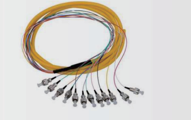
What is a custom fiber optic bundle?
A custom fiber optic bundle is a multi-channel passive assembly in which individual optical fibers are collected into a common cable or routing structure. The fibers may fan out at one end, both ends or at defined breakout points. Each channel can be terminated, labeled and tested according to the buyer’s connection map.
The word custom is important: two assemblies with the same fiber count can behave very differently if they use different fiber grades, connector polishes, fan-out lengths, jacket materials or loss acceptance limits. A useful specification therefore describes the entire assembly rather than only stating “12-core bundle.”
Fiber Optic Bundle, Ribbon, Fan-Out or Pigtail?
Quick answer: Choose a fiber bundle when several fibers must travel together as one organized assembly; choose a ribbon assembly for a flat, ordered fiber layout; choose a fan-out or breakout assembly when individual fibers need protected branches; and choose pigtails when one end is connectorized and the other end will be spliced. The correct construction depends on fiber type, core count, branch layout, termination and the equipment interface.
| Structure | Use it when | Specify | Typical termination |
|---|---|---|---|
| Fiber optic bundle | Multiple fibers share one main cable route | Fiber type, count, OD, jacket and length | Single-ended or double-ended |
| Ribbon assembly | Fiber order and compact flat routing matter | Fiber pitch/order, count, breakout and labeling | Array, module or individual connectors |
| Fan-out / breakout cable | Each fiber needs an identifiable protected branch | Trunk length, branch length, tube OD and port map | Connectorized branches at one or both ends |
| Fiber pigtail | The free end will be fusion-spliced in a termination box | Connector, polish, fiber type, buffer and pigtail length | Connector at one end; bare fiber at the other |
Fiber Bundle Selection Map
1. Does every fiber need its own protected branch?
Yes → Fan-out or breakout assembly. No → Continue.
2. Must fibers remain in a flat, fixed order?
Yes → Ribbon assembly. No → Continue.
3. Will the field end be fusion-spliced?
Yes → Pigtail or single-ended bundle. No → Double-ended connectorized bundle.
4. Is polarization alignment required?
Yes → Use a PM-specific assembly and state fast/slow-axis alignment. No → Select the required single-mode or multimode fiber.
For a configurable product reference, review our fiber optic bundle and ribbon cable assembly. If individual branches or a PM construction are required, include a branch drawing so the correct assembly family can be reviewed.
Connector, Polish and Acceptance Parameters
Connector selection must match the mating equipment and fiber type. PC, UPC and APC are not interchangeable descriptions: polish affects return loss, and APC interfaces must be mated to a compatible APC interface. For PM assemblies, also define connector-key orientation and the required fiber-axis alignment.
| RFQ item | What to state | Why it matters |
|---|---|---|
| Fiber | Single-mode 9/125 µm, multimode 50/125 µm or 62.5/125 µm, or specified specialty fiber | Controls mode, wavelength and connector compatibility |
| Core count | Required fiber count and spare fibers | Determines trunk, ribbon and branch construction |
| Connector and polish | Connector at each end; PC, UPC or APC as applicable | Must match the equipment interface and return-loss requirement |
| Lengths | Overall length, trunk length, branch length and tolerance | Prevents routing and cabinet-fit errors |
| Port map | Fiber color/order, port labels and end-to-end mapping | Avoids installation and channel-identification errors |
| Optical acceptance | Test wavelength, insertion loss, return loss and test-report requirement | Makes supplier results comparable |
| Mechanical construction | Jacket, tube OD, bend radius, tensile/crush and environment | Matches handling and service conditions |
Catalog reference: Existing configurable bundle assemblies include 9/125 µm single-mode and 50/125 µm or 62.5/125 µm multimode options, with reference counts of 4, 6, 8, 12 and 24 fibers. Reference connector values include SM PC insertion loss <0.3 dB, SM APC <0.2 dB and MM PC <0.3 dB; corresponding return-loss references are >45 dB, >60 dB and >25 dB. These are product-family references, not universal guarantees. Confirm the final fiber, connector, wavelength, test method and acceptance limit in the quotation.
Request a Custom Fiber Bundle Quote
Send the fiber type and count, connector/polish at each end, total and branch lengths, port map, jacket or tube requirement, test wavelength, acceptance limits, quantity and delivery destination. Attach a drawing when branch routing or end-to-end fiber order matters.
Seven parameters that define a fiber optic bundle
- Fiber type and wavelength: specify 9/125 µm single-mode, 50/125 µm multimode, 62.5/125 µm multimode or another fiber, together with the operating wavelength.
- Channel count: common reference counts include 4, 6, 8, 12 and 24 fibers, but the correct count follows the equipment architecture.
- Connector and polish: define the connector family, PC/UPC/APC polish, keying and adapter interface for every channel.
- Termination pattern: state whether the assembly is single-ended, double-ended or includes a bare-fiber or splice-ready end.
- Dimensions: give total trunk length, fan-out length, branch spacing, routing envelope and any tolerance that matters to installation.
- Mechanical and environmental needs: include bend radius, tensile load, temperature, jacket, abrasion, chemical exposure and flame requirements where applicable.
- Inspection requirements: define insertion-loss and return-loss limits, end-face inspection, channel identification and the required test report.
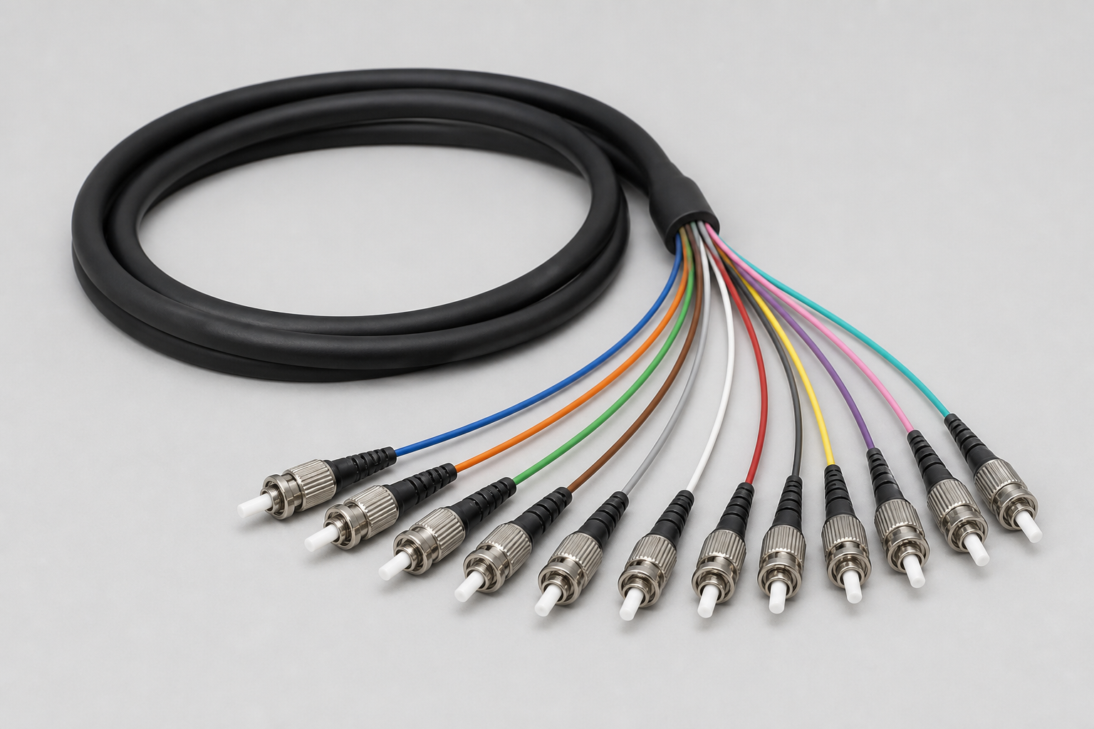
How to choose single-mode or multimode fiber
Single-mode fiber is generally selected for longer links, narrow-mode transmission and systems designed around telecom wavelengths. ITU-T G.652 describes geometrical, mechanical and transmission attributes for standard single-mode fiber and cable around the 1310 nm zero-dispersion region and use in the 1310 nm and 1550 nm regions. Multimode fiber is often used for shorter equipment, LAN, illumination or instrument links where the source, receiver and modal-bandwidth requirements are compatible.
Do not choose only by distance. The optical source, numerical aperture, launch condition, connector interface and receiver architecture may determine the correct fiber. If the equipment documentation names a fiber grade, include that designation in the RFQ.
Connector polish and return loss
| Polish | Interface characteristic | Common consideration |
|---|---|---|
| PC | Physical-contact end face | Used where the specified loss and reflectance performance are sufficient |
| UPC | Improved physical-contact polish | Often selected when lower reflection is required without angled mating |
| APC | Angled physical-contact interface | Used in reflection-sensitive systems; must mate with the correct APC interface |
Connector color alone is not an engineering specification. State the connector family and polish in the drawing, and confirm whether the assembly must mate to adapters, transceivers or instrument ports.
Insertion loss, return loss and acceptance testing
An assembly loss requirement should identify the test wavelength and whether the limit applies per connector, per channel or end-to-end. For a simple planning estimate:
Estimated channel loss = connector loss + splice loss + fiber attenuation + engineering margin
The commercial product specification should then state the measurable acceptance limit. A reference OpticLumos bundle configuration lists single-mode insertion-loss values below 0.3 dB for PC and below 0.2 dB for APC, with project-specific confirmation required. Final limits depend on the selected connector, fiber, channel layout and test method.
When do you need a polarization-maintaining fiber bundle?
For polarization-sensitive instruments, specify PM fiber rather than assuming that an ordinary single-mode bundle preserves the required polarization state. The launch must be aligned with the selected fiber axis, and connector key orientation and assembly handling need to be included in the acceptance plan.
Two cable constructions serve different routing needs:
- Multicore PM fiber bundle cable: multiple PM fibers share an outer jacket. The published reference configuration covers 4–8 fibers with optical data at 1310 nm.
- Multicore PM fiber breakout cable: individually sheathed PM subunits support separate branch routing. The published reference configuration covers 2–6 fibers with optical data at 1310 nm.
These are cable construction references, not a blanket specification for a finished connectorized assembly. Cable crosstalk per stated test length is not interchangeable with end-to-end assembly PER. Define wavelength, launch alignment, test length, connectors, bend condition and the required acceptance value. See the polarization extinction ratio guide and PM fiber jumper specifications for the related measurement and termination considerations.
How to evaluate a custom fiber bundle manufacturer
- Drawing control: the supplier should convert the channel map and dimensions into an approval drawing before production.
- Traceable inspection: request channel identification, insertion-loss results and end-face inspection where relevant.
- Configuration discipline: verify fiber grade, connector polish, labeling and polarity against the order.
- Environmental qualification: ask which tests apply to the actual application. IEC 60794-1-22 defines environmental test procedures for optical cables, including temperature-related methods.
- Change management: revisions to length, fan-out or connector mapping should be reflected in the controlled drawing and inspection plan.
Applications
Custom bundles are used in optical termination boxes, equipment rooms, industrial control and test systems, indoor LAN links, broadcast equipment, sensing instruments, astronomy and spectroscopy equipment, and compact multi-channel optical routing. The assembly should be designed around the equipment interface and installation environment rather than copied from an unrelated application.
RFQ checklist for custom fiber optic bundles
- Fiber type, grade, core count and operating wavelength
- Connector family, polish and channel-to-port map
- Single-ended or double-ended termination
- Total length, fan-out lengths and tolerances
- Maximum insertion loss and minimum return loss
- Temperature, bend, tensile, jacket and installation requirements
- Labeling, packaging, inspection and test-report requirements
- Prototype and production quantity
See the Fiber Optic Bundle & Ribbon Cable Assembly product page for reference configurations, or compare other passive fiber optic components and connectors. For a project-specific review, submit your channel map and specifications.
Frequently asked questions
Can a fiber optic bundle use both single-mode and multimode fibers?
A mixed assembly can be reviewed, but each channel must be clearly identified and matched to compatible sources, receivers and connectors. Using one fiber family throughout is simpler when the equipment permits it.
How many fibers can be included?
Reference configurations commonly include 4, 6, 8, 12 and 24 fibers. Larger or non-standard counts depend on the cable diameter, fan-out space, connector density and handling requirements.
Should the bundle be terminated at one end or both ends?
Either is possible. Single-ended assemblies can suit termination boxes or splice workflows, while double-ended assemblies provide a finished connector map between two pieces of equipment.
What documents should accompany a custom assembly?
A practical documentation package may include the approved drawing, channel map, inspection record, optical test results, labeling list and packaging requirements.
What is the most important information for a quotation?
Start with fiber type, channel count, connector map, lengths, optical limits, environment and quantity. A drawing or port map greatly reduces ambiguity.
Selection guidance updated: September 2026. Final cable and assembly requirements should be confirmed against the approved drawing and test plan.
Technical references
- ITU-T G.652 — Characteristics of a single-mode optical fibre and cable
- IEC 60794-1-22 — Environmental test methods for optical fibre cables