
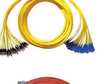
Custom Fiber Optic Fan-Out & Branch Cable Assembly
Quick answer: A custom fiber optic fan-out cable assembly routes multiple single-mode or multimode fibers through one main cable and separates them into identifiable connectorized branches. Specify fiber type, count, trunk and branch lengths, port mapping, connectors, polish and optical acceptance limits.
This construction is intended for ordinary SM/MM equipment interconnection, termination boxes, control systems and indoor network links. It is distinct from flat ribbon assemblies and polarization-maintaining breakout cables.
Product Features
Fan-Out, Branch Cable or Pigtail?
Compare grouped and ribbon constructions on the Fiber Optic Bundle & Ribbon Cable Assembly page. For polarization-sensitive channels, review the PM Fiber Breakout Cable.
Reference Specifications
| Characteristic | Unit | Single-mode | Multimode |
|---|---|---|---|
| Fiber / core diameter | µm | 9/125 | 50/125 or 62.5/125 |
| Insertion loss | dB | PC <0.3; APC <0.2 | PC <0.3 |
| Return loss | dB | PC >45; APC >60 | PC >25 |
| Insertion/withdrawal durability | cycles | 1,000 cycles; loss change <0.3 dB | |
| Reference temperature range | °C | -40 to +80 | |
| Reference tensile strength | kgf | 15 | |
Reference catalog values only. Final fiber grade, connector, polishing, test wavelength, construction, length and acceptance limits must be confirmed in the approved quotation and drawing.
Reference Product Constructions
Single-mode fan-out referenceConnector family, branch count, color coding and dimensions are project-specific.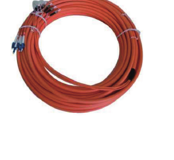 Multimode branch referenceFinal fiber grade, termination and branch layout follow the approved drawing.
Applications
Termination Drawing & RFQ Checklist
A dimensioned routing and port-map drawing is recommended whenever channel order matters.
- Fiber type, grade, count and operating wavelength
- Connector and PC, UPC or APC polish at each end
- Total trunk length, breakout location, branch lengths and tolerances
- Branch tube or jacket diameter, bend radius and installation environment
- Color sequence, labels and end-to-end port mapping
- Insertion-loss and return-loss limits with test wavelength and method
- Quantity, packaging, drawing approval and requested test report
Frequently Asked Questions
How is this different from a bundle or ribbon assembly?
This page focuses on individually routed connectorized branches and a controlled port map. A bundle groups fibers, while ribbon keeps fibers in a flat fixed order.
Can it use single-mode or multimode fiber?
Reference designs support either fiber family. Mixed-fiber assemblies require unambiguous channel identification and equipment compatibility review.
Are connectors included?
The assembly may be connectorized at one or both ends. State the connector family and polish for every port; a bare or splice-ready end can also be reviewed.
What should the branch drawing show?
Show trunk and branch lengths, breakout locations, branch protection, fiber order, port labels, connectors, tolerances and routing constraints.
Related Products & Guides
Request a Custom Fan-Out Assembly Quote
Send the fiber count, connector map, trunk and branch lengths, polishing, loss limits, environment, quantity and a routing drawing for technical review.