

The minimum bend radius of a fiber optic cable is a property of a specified cable construction under specified conditions. It is not one universal number for every patch cord, armored sensing cable or multi-fiber assembly. A useful ordering drawing connects the cable data to the actual tray, boot clearance and service-loop space.
What Is Fiber Optic Cable Bend Radius?
Bend radius describes the curvature of a cable route. Bend diameter describes the size of the corresponding circular bend or loop. Cable outside diameter, often written OD, is the thickness of the cable itself. They are three different dimensions.

The Fiber Optic Association’s bend-radius reference explains the radius/diameter distinction and gives common installation and relaxed-cable examples. It also warns that some cable constructions use different multipliers. Do not turn a planning rule of thumb into an acceptance limit without checking the actual cable data.
Installation Bend Radius vs Installed Bend Radius
| Condition | Information needed | Where it belongs on the drawing |
|---|---|---|
| Installation / loaded | Minimum bend radius under the permitted pulling load; maximum tensile load and approved pulling arrangement | Pulling route, transitions, rollers or other installation hardware |
| Installed / unloaded | Minimum sustained routing radius after pulling load is removed | Trays, cabinet turns, closures and stored slack |
| Repeated flexing or motion | Qualified flex conditions, cycle count, speed, temperature and acceptance criteria where applicable | Moving section and strain-relief arrangement |
Corning’s duct-installation procedure, SRP 005-011 distinguishes loaded and installed cable limits and directs users to the cable-specific specification. Its tables include different limits for different constructions. This is why a generic multiplier should not override the approved part specification.
For a moving assembly, ask for its qualified flex conditions separately. An installed-radius number is not, by itself, evidence of suitability for a cable chain or repeated winding. Record the motion requirement explicitly instead of leaving it implicit in the word “flexible.”
How to Calculate Minimum Bend Radius: A Worked Example
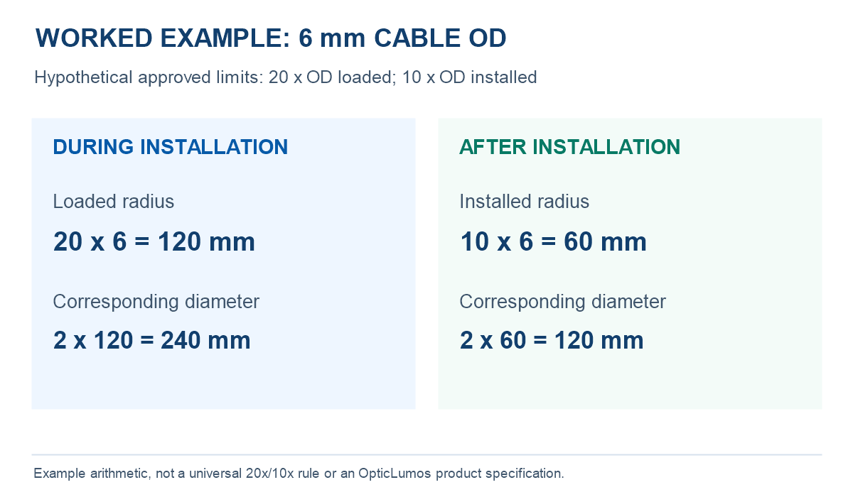
- Loaded radius: 20 × 6 mm = 120 mm; corresponding bend diameter = 240 mm.
- Installed radius: 10 × 6 mm = 60 mm; corresponding bend diameter = 120 mm.
- Space check: A 100 mm-diameter storage loop has a radius of 50 mm. It does not meet this example’s 60 mm installed minimum.
The 120 mm figure is the geometric bend diameter using the chosen radius reference, not a guaranteed outside envelope for a complete cable loop. Add the applicable cable thickness, guides, ties and dimensional tolerances when checking the physical compartment.
A Simple Review Worksheet
| Input or check | Example value | Review question |
|---|---|---|
| Documented cable OD | 6 mm | Is this the actual ordered jacket/construction? |
| Installed minimum radius | 60 mm | Is the value a radius or a diameter? |
| Proposed loop diameter | 100 mm | Does its 50 mm radius meet the limit? No. |
| Revised route | At least the required bend geometry, plus physical clearance | Have hardware, cable thickness and tolerance been included? |
This worksheet is an engineering review example, not a substitute for installation approval. The route must also satisfy the specified pulling, crush, torsion and environmental limits.
MPO Trunks, Fanout Branches and Specialty Cables Need Local Checks
A custom assembly can contain several mechanically different sections. Review them individually rather than assigning the largest cable’s number to every feature or using a thin branch’s flexibility to justify a tight trunk route.
- MPO trunk: Check the main cable, boot exit and space needed to operate the connector. A dense panel drawing should show the service loop and connector access, not only port pitch.
- Breakout or fanout: Show the breakout body, individual protected legs, branch lengths and strain-relief points. Confirm local routing limits for each section.
- Armored or outdoor cable: Obtain limits for the exact jacket, armor and strength-member construction. Do not infer a finished-cable limit from the underlying glass fiber alone.
- PM or sensing cable: Agree the required optical or sensing checks after routing and environmental conditioning, in addition to dimensional compliance.
For product review, compare MPO trunk and breakout assemblies, custom fan-out and branch cable assemblies and bundle and ribbon assemblies. The linked pages identify construction options; the approved drawing must establish the actual routing limits.
Does Bend-Insensitive Fiber Remove the Cable Limit?
No. Treat a bend-insensitive fiber designation as one part of the optical specification. The finished assembly still has its own jacket, protection, termination and mechanical requirements. Ask separately for the fiber’s optical bend-loss conditions and the finished cable’s handling limits; do not substitute one for the other.
For a loss investigation, use the fiber attenuation guide to separate routing questions from other loss sources. A 300 m 10G-SR link check also needs the full optical budget; length compliance alone does not approve the route.
Bend-Radius and Routing RFQ Checklist
Send a dimensioned route sketch with the cable type, OD, fiber count, connector/boot geometry, installed and installation conditions, motion or reeling requirement, temperature, branch arrangement and optical acceptance criteria.
Example request: “Our enclosure provides a proposed 150 mm loop diameter. Please identify the approved installed and loaded minimum bend radii for the quoted cable, confirm the radius reference and required physical clearance, and review the attached connector-exit and breakout drawing. State any separate restrictions on pulling, repeated flexing or storage.”
Do not request only “a flexible fiber cable.” A quoted construction, a measurable route and an agreed acceptance plan make the response useful. For field sensing installations, also review the DTS cable installation guide.
Frequently Asked Questions
Is 10 times the cable diameter always acceptable?
No. It is a common example for some installed cables, not a universal minimum. Use the approved limit for the exact construction and condition.
What is the difference between bend radius and loop diameter?
For the corresponding circular geometry, the diameter is twice the radius. Cable OD is a separate input. Check the supplier’s dimensional reference when converting the drawing.
Can the cable pass an optical test but still violate the drawing?
Yes. A measured optical result and dimensional compliance are different acceptance items. Review both rather than using one as a substitute for the other.
Need a Cable That Fits Your Actual Route?
Send the route sketch, available loop space, cable and branch dimensions, environment and test requirements. OpticLumos can review a suitable construction and confirm the approved limits before quotation.