

Fiber optic connector cleaning belongs in the connection and acceptance process, alongside interface checks and optical measurements. For an MPO trunk, an LC fanout or an SC patch lead, use an inspection-led process rather than assuming a new cable or a fitted dust cap proves the endface is ready.
How to Clean Fiber Optic Connectors Without Losing the Inspection Record
Start with the equipment manufacturer’s work instruction. Cisco’s inspection and cleaning procedure calls for optical sources to be switched off before inspection and distinguishes dry cleaning from wet cleaning. Never look into a fiber or an optical port. Use an appropriate video inspection system and the site’s optical safety procedure.
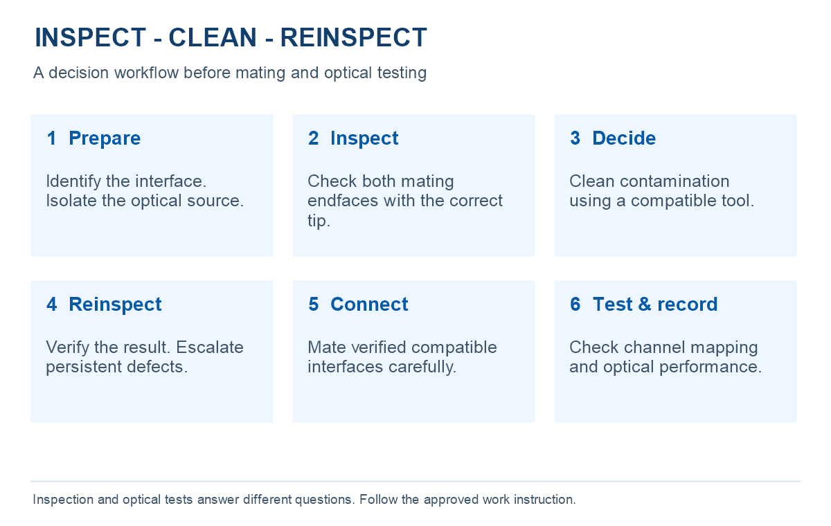
- Identify the interface. Record connector family, polish, fiber type and the port or cable identifier. The inspection tip must reach the actual endface correctly.
- Inspect both sides. Include the cable plug and the mating port, together with the reference leads used for acceptance. Keep the before image when investigating a failure.
- Clean when required. Use the compatible tool and fresh cleaning media as instructed. If contamination remains, use the manufacturer’s permitted escalation method; do not improvise solvent quantity or increase force.
- Reinspect. Confirm the cleaning result. Record persistent marks separately from removable debris and escalate them for technical review rather than repeating cleaning indefinitely.
- Mate and verify. Confirm the intended interfaces and channel map, then run the agreed optical tests. Preserve the final images and results under the same assembly identifier.
Fluke Networks’ cleaning and inspection guidance explains that factory-terminated connectors and dust-capped ports still require inspection. It also cautions against unnecessary cleaning of an endface that already meets the applicable inspection criteria.
Choose a Cleaning Tool for the Actual Interface
| Interface | Tool-selection check | Information to confirm |
|---|---|---|
| LC / MU single-fiber interface | Common cleaner format: 1.25 mm ferrule | Exposed plug or recessed port; polish; approved tip and cleaning method |
| SC / FC / ST single-fiber interface | Common cleaner format: 2.5 mm ferrule | Connector access, port depth and compatibility with the specific cleaner |
| MPO interface | Dedicated multi-fiber cleaner and inspection tip | Base-12 or Base-16 geometry, row count, pin arrangement, polish and plug/port access |
Fluke’s guidance lists separate single-fiber and MPO cleaner formats. Treat that as a compatibility check, not permission to use one cleaner on every rectangular ferrule. Follow the tool supplier’s stated interface coverage.
MPO Connector Cleaning: Inspect More Than One Fiber Core
An MPO ferrule presents several fibers within one shared contact surface. VIAVI’s MPO testing guidance explains how contamination can interfere with contact across neighboring fibers and why cleaning must be followed by inspection. A single sharp-looking core image is therefore insufficient evidence for the entire interface.
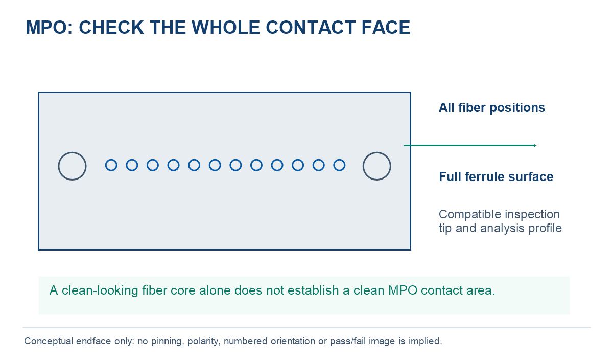
The public scope of IEC 61300-3-35:2022 addresses debris, scratches and defects, including contamination over the whole rectangular ferrule contact surface. It explicitly separates visual inspection from optical qualification. The edition also states that visual failure alone does not determine rejection: specified optical performance matters.
For procurement, agree the inspection profile and the disposition of persistent defects before shipment. Do not copy an old single-fiber inspection chart into an MPO acceptance sheet. Record the instrument, applicable profile and result alongside the optical report.
A Practical Acceptance Record for an MPO-to-LC Assembly
The following is a proposed record structure, not a claim that a particular assembly has passed these checks. Use one assembly ID across the drawing, inspection files and test report so a result can be traced to the delivered item.
| Record field | What the buyer and supplier should agree |
|---|---|
| Assembly identity | Part number, revision, sample/production lot, serial or cable ID and approved drawing |
| Endface inspection | Plug/port identifier, inspection profile, relevant images, result and corrective action |
| Channel identity | MPO position to LC branch mapping, labels and duplex pairing |
| Optical acceptance | Per-channel IL and any required RL limits, wavelengths, direction and reference method |
| Release decision | Final result, unresolved deviations and authorized technical disposition |
Example RFQ wording: “Please review the attached MPO-to-LC assembly drawing. Confirm the MPO interface, pinning, polish and channel map, and identify the inspection profile used for the finished endfaces. Supply channel-level optical results at our stated wavelengths and limits. Link the inspection and test records to the assembly ID.”
Insert the actual limits and reporting requirements from your application. This example does not guarantee a particular loss grade or inspection service for every configuration.
Use the MPO-to-LC breakout selection guide for the ordered channel map and insertion loss vs return loss for measurement definitions. Compare the MPO connector and assembly configurations, LC connector components and SC connector components when specifying the interfaces.
Frequently Asked Questions
Does a dust cap mean a connector is clean?
No. Inspect before mating, including new or previously protected interfaces. A dust cap protects handling but is not an inspection result.
Can an LC cleaning pen clean an MPO connector?
Do not assume compatibility. MPO needs a tool that explicitly supports its ferrule geometry and access arrangement; an LC tool is intended for a different interface.
Does a clean endface prove the MPO polarity is correct?
No. Cleanliness, pinning and channel mapping are separate checks. Verify the map against the drawing and use the MPO polarity guide for the interface convention.
Should a connector with a persistent mark automatically be scrapped?
Escalate it under the agreed inspection and optical qualification process. Do not confuse removable contamination, a persistent surface feature and a failed optical measurement.
Need a Traceable Connector Assembly Specification?
Send the interface drawing, channel map, fiber grade, length and acceptance requirements. OpticLumos can review the configuration and confirm the applicable inspection and test records before quotation.