
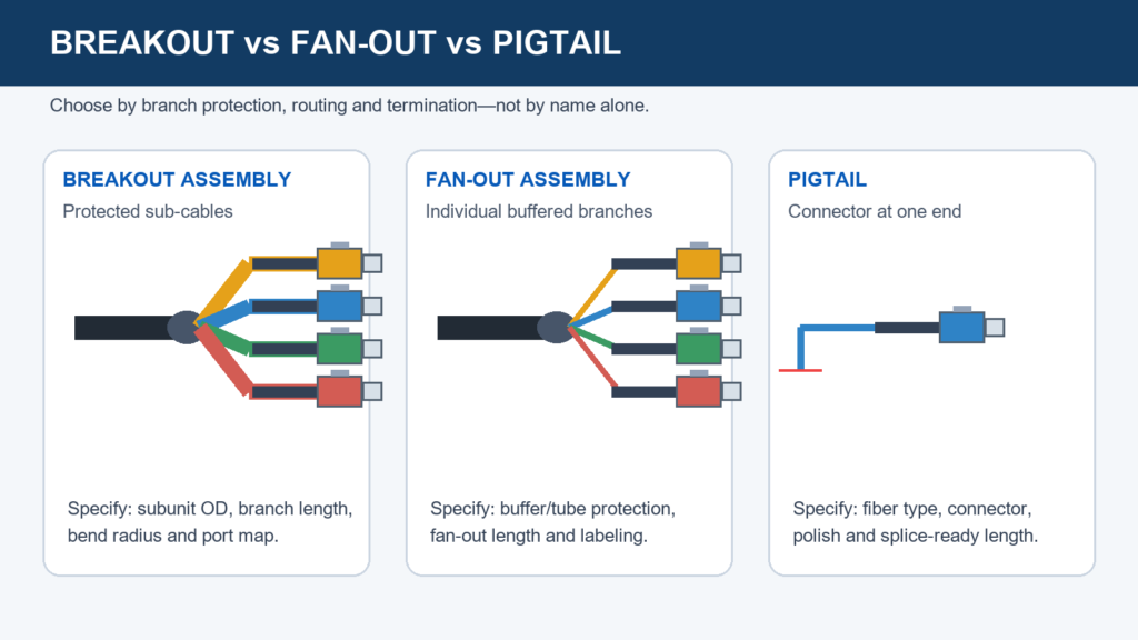
“Breakout,” “fan-out,” and “pigtail” describe different construction and termination choices. Using the wrong term in an RFQ can produce the wrong branch protection, connector count, or installation method even when the fiber count is correct.
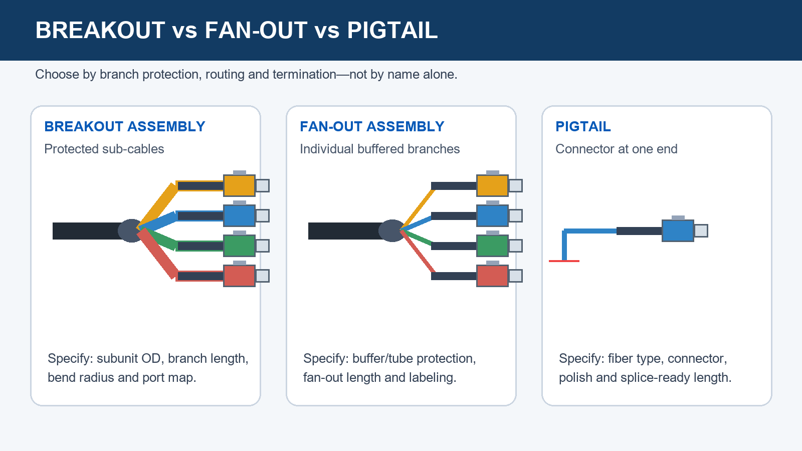
Breakout vs fan-out vs pigtail at a glance
| Format | Construction | Termination | Best fit | Key RFQ detail |
|---|---|---|---|---|
| Breakout cable | Individually buffered or jacketed subunits inside one outer jacket | May be connectorized at either or both ends | Repeated handling, long exposed branches and field routing | Subunit OD, outer jacket, branch length and breakout method |
| Fan-out assembly | Common trunk transitions into protected legs | Usually a finished, connectorized assembly | Racks, modules, instruments and port routing | Breakout-point location, leg length, connector and port map |
| Pigtail set | Individual fibers or ribbon/loose-tube set prepared for splicing | Connector on one end; bare or prepared fiber on the other | Splice trays, closures and ODFs | Strip length, identification and splice-side preparation |
What the three terms mean in practice
Breakout cable: protection follows every fiber
A true breakout cable carries several reinforced subcables under a common jacket. After the outer jacket is removed, the subunits can usually be routed farther and handled more often than bare 250 µm fibers. It suits portable systems, exposed routing and installations where each channel must behave like a small cable.
Fan-out assembly: one trunk, one transition, many legs
A fan-out assembly divides a compact trunk at a controlled transition into separate legs. The transition may be overmolded, heat-shrunk or housed in a breakout body. Legs can have different lengths, labels and connector types. See the custom fiber optic fan-out cable assembly for configurable options.
Pigtail: a splice-ready end condition
“Pigtail” primarily describes termination: one connectorized end and one splice-ready end. A pigtail can use single fibers, ribbon or a grouped construction. It is normally protected inside a tray or enclosure after splicing and should not be assumed to provide the same branch strength as a jacketed breakout leg.
Fan-out kit vs finished fan-out assembly
Search results frequently use fiber fan out kit for small tubes, boots and heat-shrink parts that protect loose 250 µm fibers as they leave a cable. The installer still performs the breakout, termination and testing. A finished fan-out assembly arrives with the transition, branches, connectors, labels and test results defined.
Four steps to select the construction
- Start with handling. Decide whether the branch will remain in a protected tray, route independently inside equipment, or be moved repeatedly. This sets the mechanical construction.
- Define geometry. Specify overall length, trunk length to the breakout datum, every leg length, tolerances and whether measurements end at the connector tip, boot or transition.
- Map every fiber. Provide fiber color/number, end-A connector, end-B connector, equipment port and label. Add the viewing direction for keyed or polarity-sensitive interfaces.
- Set acceptance limits. State fiber type, operating and test wavelengths, maximum insertion loss, minimum return loss where relevant, polish, temperature, bend radius and flex/pull requirements.
What the assembly drawing must show
- Trunk cable type, OD, jacket material, color and print legend.
- A fixed reference point for the breakout transition and tolerances on both sides.
- Numbered legs with individual lengths, tubing OD and label positions.
- Connector family, polish, boot, key orientation and dust caps.
- End-A to end-B port map; for pigtails, strip or splice-preparation length.
- Pulling eye, gland, conduit or panel-entry hardware when required.
For dense or unusual geometries, compare the fiber optic bundle cable assembly and the broader fiber bundle selection guide.
Connector and optical acceptance
| Parameter | Why it matters | What to specify |
|---|---|---|
| Fiber and wavelength | Loss and mode behavior depend on both | Fiber designation plus operating and test wavelengths |
| Insertion loss | Controls the forward power budget | Maximum per channel and reference method |
| Return loss | Limits reflected power | Minimum per terminated channel and method |
| Connector polish | PC, UPC and APC are different interfaces | Exact connector/polish at each end |
| End-face criteria | Contamination or damage can dominate field loss | Inspection and cleaning before final test |
IEC 61300-3-4:2023 describes attenuation measurement methods for passive fiber-optic components. IEC 61300-3-35:2022 addresses visual examination of connector end faces. State the agreed edition and method; “low loss” alone is not an acceptance specification.
Worked RFQ example
Assembly: 12-fiber single-mode trunk to 12 simplex legs; 8.0 m overall; breakout at 6.5 m from end A; legs 1.5 m from transition to connector tip; ±50 mm leg tolerance.
Termination: LC/UPC on all legs, numbered 01–12; end A prepared for fusion splicing with 1.0 m accessible fiber; include a port map and serialized test report.
Acceptance: test every channel at 1310 nm and 1550 nm and inspect end faces before shipment. Agree final limits for the connector and reference method.
Common specification failures
- Calling a finished harness a “fan-out kit,” inviting a quote for un-terminated parts.
- Giving only total length and omitting the breakout datum.
- Naming connectors without polish or orientation.
- Omitting the channel map because both ends have the same count.
- Giving one loss number without wavelength, method or channel basis.
- Using unprotected pigtails where branches will be moved or pulled.
RFQ checklist
- Assembly type: breakout, finished fan-out or pigtail set
- Fiber count and exact SM, MM, PM or specialty fiber
- Trunk OD/jacket, branch tubing and bend radius
- Overall, trunk and leg lengths with datums and tolerances
- Connector, polish, key, boot and cap for every port
- Channel map and label text
- Test wavelengths, IL and RL limits
- Temperature, flex, pull, flame and ingress requirements
- Packaging, report and drawing approval
For PM branches, review the multicore PM fiber breakout cable. For harsh outdoor mating, use a purpose-designed ODC outdoor assembly.
Frequently asked questions
Is a fiber fan-out kit the same as a fan-out cable assembly?
No. A kit generally supplies furcation tubes and transition parts for field termination. A finished assembly includes the breakout, protected legs, connectors, labels and defined tests.
Can a pigtail have more than one fiber?
Yes. Pigtail sets and ribbon pigtails can contain multiple fibers; the defining feature is a connectorized end and a splice-ready end.
When is breakout cable better than fan-out tubing?
Choose breakout construction when each exposed branch needs higher crush, handling or routing protection.
What prevents port-mapping errors?
Provide a numbered end-A-to-end-B table, fiber identifiers, connector orientation and drawing view. Require continuity checking against the map.
References
Need a buildable fan-out drawing?
Send the fiber count, construction, length sketch, connectors, port map and acceptance limits. OpticLumos can review the configuration and prepare a custom assembly quotation.