
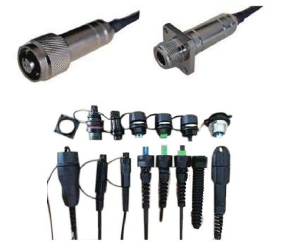
ODC Outdoor Pre-Terminated Fiber Optic Cable Assembly
Quick answer: An ODC outdoor pre-terminated fiber optic cable assembly uses a threaded, keyed connector interface and sealed cable termination for fast equipment connection in exposed installations. Define the plug and receptacle interfaces, core count, fiber type, cable length, routing conditions and acceptance tests before ordering.
Reference configurations support 2, 4, 6 or 8 fibers for FTTA, sensing, railway, industrial and other outdoor communication links. Final sealing and environmental requirements are confirmed for the selected project construction.
Product Features
ODC Interface Selection Map
Reference Specifications
| Characteristic | Unit | Reference specification |
|---|---|---|
| Insertion loss | dB | ≤0.70 |
| Repeatability | dB | ≤0.50 |
| Fiber count | cores | 2, 4, 6 or 8 |
| Mating durability | cycles | ≥500 |
| Operating temperature | °C | -40 to +85 |
Reference catalog values only. Final optical limits, fiber and cable type, connector configuration, sealing test, dimensions and environmental acceptance criteria must be stated in the approved project specification.
Outdoor Sealing & Compatibility
The reference design is described as waterproof, dustproof and corrosion-resistant, but the source document does not state an IP67 or IP68 certification. Include the required ingress, temperature, vibration, salt-mist or other environmental test standard in the RFQ. Mechanical fit, keying and optical mapping must be confirmed from interface drawings; no third-party brand compatibility is implied.
Applications
Pre-Terminated Assembly RFQ Checklist
- Required fiber count, fiber grade and operating wavelength
- Plug and receptacle arrangement, panel cutout and interface drawings
- Connector keying, mating orientation and end-to-end channel map
- Cable length, jacket, minimum bend radius and pulling conditions
- Operating temperature, water, dust, corrosion and mechanical exposure
- Maximum insertion loss, repeatability, mating-cycle and test-report requirements
- Quantity, packaging, delivery destination and installation constraints
Frequently Asked Questions
Does ODC mean the assembly is automatically IP67 or IP68?
No fixed IP rating is claimed from the available source data. State the required ingress-protection test and acceptance standard so the selected configuration can be reviewed.
Which fiber counts are available?
The source catalog lists reference configurations with 2, 4, 6 and 8 fibers. Other requirements are subject to engineering review.
Can the assembly reduce field splicing?
Yes. A pre-terminated plug and equipment-side receptacle can provide direct mating. The actual installation plan and any remaining splice points must be defined in the project drawing.
What controls equipment compatibility?
Compatibility depends on connector geometry, keying, panel interface, mating orientation, fiber type and the end-to-end channel map. Confirm all of these from drawings before production.
Related Products & Resources
Request an ODC Outdoor Assembly Review
Send the core count, fiber and cable type, plug/receptacle drawings, length, environment, optical limits, quantity and required sealing tests for a project-specific quotation.