
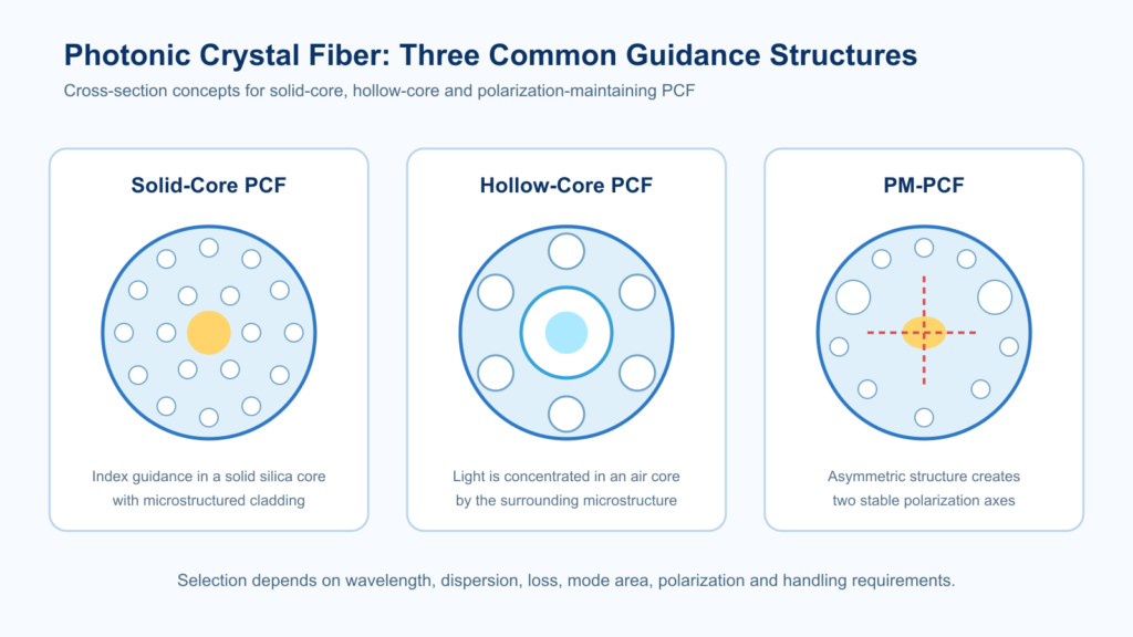
Photonic crystal fiber (PCF) is a microstructured optical fiber that uses a precisely arranged pattern of longitudinal air holes to control light guidance, dispersion, mode area, birefringence and nonlinear interaction. Depending on the core design, a PCF can guide light in solid silica through modified total internal reflection or in a hollow core through anti-resonant or photonic-bandgap effects.
Quick answer for engineers and buyers: choose a PCF by matching the guiding mechanism, operating wavelength, mode-field diameter, numerical aperture, attenuation, dispersion, bend sensitivity, polarization requirement, power level and delivery format to the application. A mechanically compatible fiber is not necessarily optically suitable, so the RFQ should state both system conditions and acceptance tests.
Key PCF selection points
- Start with the operating wavelength and required guiding mechanism.
- Compare mode-field diameter, NA and dispersion at the actual wavelength—not only nominal values.
- Define whether polarization maintaining, high nonlinearity, large mode area or hollow-core guidance is required.
- Include coupling, splicing, coating, minimum bend radius and termination requirements.
- Request test data that represents the delivered fiber length or assembly.
What is photonic crystal fiber?
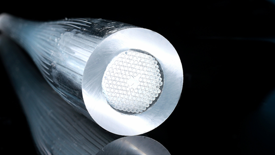
Photonic crystal fiber is an optical fiber whose cross-section contains a designed microstructure, normally a periodic or non-periodic arrangement of air holes running along the fiber. Conventional step-index fiber mainly controls light with a solid core and cladding of different refractive indices. PCF adds geometric control: air-hole diameter, pitch, core shape, number of rings and glass composition can be adjusted to produce optical behavior that is difficult to achieve in conventional fiber.
The term PCF covers several different products rather than one universal fiber. Solid-core PCF, hollow-core anti-resonant fiber, highly nonlinear PCF, large-mode-area PCF and polarization-maintaining PCF solve different engineering problems. Selection must therefore be based on the application and measured parameters instead of the PCF label alone.
For a direct engineering comparison of guiding mechanism, loss, bend sensitivity, power handling, dispersion and termination, read our solid-core vs hollow-core photonic crystal fiber selection guide. It includes an application matrix and RFQ checklist for choosing between the two fiber families.
How does photonic crystal fiber guide light?
Modified total internal reflection in solid-core PCF
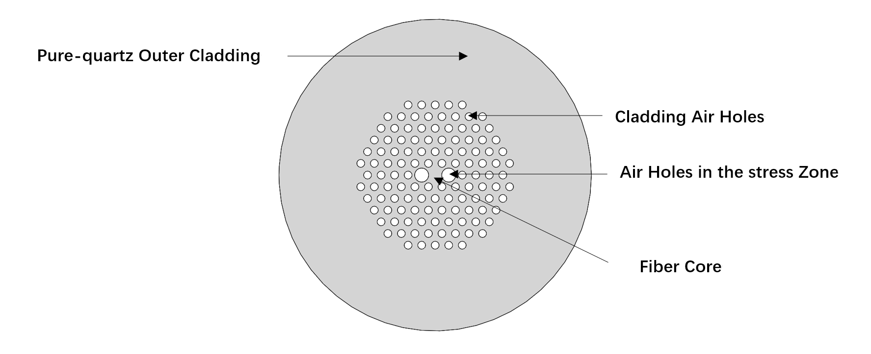
A solid-core PCF normally has a silica core surrounded by a microstructured cladding with air holes. The air-filled region lowers the effective refractive index of the cladding, allowing the solid core to guide light. By controlling the ratio of air-hole diameter to pitch, the design can influence single-mode behavior, confinement, effective mode area and dispersion.
Anti-resonant and photonic-bandgap guidance in hollow-core PCF
Hollow-core fibers guide most optical power in an air or gas-filled core. In anti-resonant designs, thin glass membranes surrounding the core inhibit coupling into the cladding over defined transmission bands. Photonic-bandgap designs use a periodic cladding structure that prevents propagation in selected wavelength regions. The usable band, bend loss and modal behavior depend strongly on geometry and operating wavelength.
Main types of photonic crystal fiber
| PCF type | Primary design objective | Typical applications | Key selection items |
|---|---|---|---|
| Solid-core PCF | Flexible mode and dispersion control | Research, broadband transmission, sensing | Wavelength, MFD, NA, dispersion, attenuation |
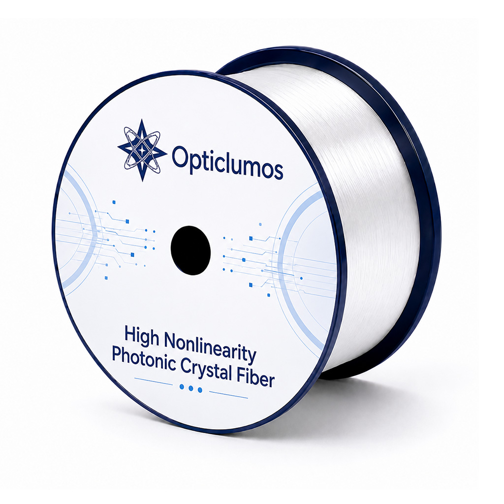
| Highly nonlinear PCF | Strong optical nonlinearity in a small effective area | Supercontinuum generation, pulse compression, wavelength conversion | Nonlinear coefficient, dispersion, launch conditions, damage risk |
| Large-mode-area PCF | Larger effective area and reduced nonlinear effects | High-power laser delivery and amplifiers | Mode area, bend sensitivity, modal purity, power handling |
| PM-PCF | Maintain a defined polarization axis | Interferometry, sensors, lasers and polarization-sensitive systems | Birefringence, beat length, PER/cross-talk and axis alignment |
| Hollow-core anti-resonant fiber | Guide light mainly in a hollow region | Gas interaction, low-latency delivery, specialty laser transport | Transmission bands, bend loss, mode content, termination |
Photonic crystal fiber vs conventional optical fiber
| Comparison item | Photonic crystal fiber | Conventional fiber |
|---|---|---|
| Guiding structure | Microstructured air-hole cladding or hollow core | Primarily solid core/cladding index profile |
| Design flexibility | Geometry can tailor dispersion, mode area, birefringence and confinement | Mature standardized designs for common transmission needs |
| Handling | May require specialized cleaving, coupling, splicing and sealing | Established tools and processes are widely available |
| Best fit | Applications needing optical behavior unavailable from standard fiber | Cost-effective, repeatable conventional communication and sensing links |
PCF should not automatically replace conventional fiber. If a standard single-mode or multimode fiber meets the optical, mechanical and environmental requirements, it may provide simpler termination and lower integration risk. PCF is most valuable when its engineered microstructure solves a defined system problem.
Key specifications for selecting PCF
Operating wavelength and transmission band
Confirm the complete wavelength range rather than only the laser center wavelength. Hollow-core designs may have discrete transmission windows, while solid-core designs can show strong wavelength-dependent dispersion and confinement loss.
Mode-field diameter, effective mode area and numerical aperture
These values affect coupling efficiency, launch optics, splice compatibility, intensity and nonlinear interaction. Measurement definitions and wavelength must be stated because values are not directly comparable without test conditions.
Dispersion and nonlinearity
For supercontinuum generation, pulse delivery and wavelength conversion, specify the dispersion profile, zero-dispersion wavelength and nonlinear requirements. The launched pulse width, peak power, repetition rate and fiber length are also necessary for a realistic recommendation.
Attenuation, confinement and bend loss
Loss should be defined at the application wavelength and representative length. Minimum bend radius, coil diameter and packaging conditions can materially affect delivered performance, particularly for hollow-core and large-mode-area structures.
Polarization performance
For PM-PCF, specify the required axis orientation, beat length or birefringence and the required assembly-level polarization extinction ratio under stated launch, wavelength, length and bend conditions.
Mechanical construction
Cladding diameter, coating diameter, coating material, proof test, temperature range and delivery format affect handling and integration. Confirm whether the requirement is bare fiber, spool, cable, pigtail, patch cord or custom terminated assembly.
Common applications of photonic crystal fiber
- Supercontinuum generation: highly nonlinear PCF combines engineered dispersion and high optical intensity for broadband spectral generation.
- High-power laser delivery: large-mode-area or hollow-core designs can reduce selected nonlinear interactions, subject to mode and bend control.
- Gas spectroscopy and sensing: hollow cores can create extended interaction between guided light and a gas or sample.
- Interferometric and polarization-sensitive systems: PM-PCF supports defined polarization axes when launch and termination are correctly controlled.
- Research and metrology: tailored dispersion, modal behavior and birefringence support experimental optical systems.
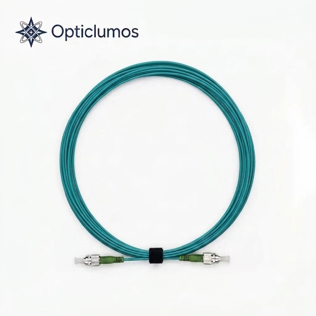
- Specialty assemblies: PCF can be supplied in pigtails or patch-cord formats when the connector, sealing, mode matching and acceptance tests are specified.
How to select photonic crystal fiber
- Define the system objective. State whether the priority is nonlinear conversion, low overlap with glass, polarization control, large mode area, sensing or another function.
- Specify the optical source. Include wavelength range, linewidth, pulse duration, repetition rate, average/peak power and beam quality where applicable.
- Define interface requirements. Provide launch optics, target MFD/NA, connector or splice requirements and acceptable insertion loss.
- Describe the mechanical environment. Include routing, bend radius, temperature, vibration, length and packaging constraints.
- Set acceptance criteria. State which parameters must be measured on the delivered fiber or assembly and under what conditions.
Coupling, splicing and handling considerations
PCF integration can be more sensitive than standard fiber integration. Cleave quality, end-face contamination, launch alignment and mode matching affect coupling loss and modal purity. Fusion splicing may require customized arc power, duration, gap and collapse control to prevent deformation of the air-hole structure. Hollow-core fibers may also require sealing or controlled termination so contamination and moisture do not enter the microstructure.
For assemblies, define connector type, polish, key orientation, end-cap or sealing method, pigtail length and test wavelength. A low-loss laboratory launch does not guarantee the same performance after cabling or connectorization, so acceptance data should represent the delivered format.
What to include in a PCF RFQ
- Application and desired optical function
- Operating wavelength or full wavelength range
- CW or pulsed source, including power and pulse parameters
- Preferred PCF type, if known
- MFD/effective area, NA, dispersion and attenuation requirements
- Polarization requirement and test conditions
- Fiber length, coating, bend radius and operating temperature
- Bare fiber, spool, pigtail, patch cord or custom assembly
- Connector, splice, axis orientation and sealing requirements
- Requested inspection report and acceptance tests
Related OpticLumos PCF products
- High-nonlinearity photonic crystal fiber for nonlinear optics and broadband-source applications.
- Polarization-maintaining photonic crystal fiber for polarization-sensitive systems.
- Square-core specialty fiber for applications requiring tailored core geometry.
- Hollow-core anti-resonant fiber patch cord for terminated hollow-core delivery.
- Browse the OpticLumos product portfolio or send application and test requirements through our technical RFQ form.
Frequently asked questions
Is every photonic crystal fiber endlessly single mode?
No. Endlessly single-mode behavior applies to particular solid-core geometries and design conditions. It should not be assumed for every PCF, especially hollow-core, high-NA or intentionally multimode designs.
What is the difference between solid-core and hollow-core PCF?
Solid-core PCF guides light mainly in glass using an effective-index difference created by the microstructured cladding. Hollow-core PCF guides most power in an air or gas-filled core using anti-resonant or photonic-bandgap effects.
Can PCF be fusion spliced to conventional fiber?
Often yes, but the process may require mode-field matching and customized splice parameters. Air-hole collapse, core alignment and geometry mismatch can increase loss or change optical performance.
Which PCF is used for supercontinuum generation?
A highly nonlinear PCF with a dispersion profile matched to the pump wavelength and pulse conditions is commonly used. Fiber length, zero-dispersion wavelength, coupling efficiency and damage limits must be considered together.
Can photonic crystal fiber be connectorized?
Yes, depending on the design and application. The connector, end-face preparation, sealing, alignment and acceptance tests should be agreed before assembly.
What data should be requested with delivery?
Useful data may include geometry, attenuation, transmission spectrum, MFD/NA, dispersion, polarization performance, length and assembly insertion loss. The required data depends on fiber type and should state the test wavelength and conditions.
Technical references and scope
- Birks, Knight and Russell: Endlessly single-mode photonic crystal fiber, Optics Letters (1997) — original research on single-mode guidance and practical bend-loss limits.
- NKT Photonics: Supercontinuum generation in photonic crystal fibers — application guidance on pump conditions, dispersion and fiber selection.
These references explain general PCF principles; they are not test reports or performance guarantees for OpticLumos products. Use the selected product datasheet and agreed acceptance tests for procurement.
Discuss your PCF requirement
OpticLumos supports specialty-fiber selection and custom delivery formats for research, laser, sensing and industrial optical systems. For a technical recommendation, send your wavelength, source, mode, polarization, length, termination and test requirements.
Written by Carl, Senior Fiber Optics Industry Specialist. Technically reviewed by the OpticLumos product team. Last reviewed: August 2026.