
MPO fiber count is a capacity choice, not a speed rating. Specify the optical interface first, then decide how many fibers your trunk must carry and how they will reach the equipment.

Compare active fibers, ferrule positions and trunk capacity
“MPO-8” is often used for an assembly with eight populated positions in the familiar 12-position interface. Therefore, ask for the ferrule drawing and occupied positions rather than relying on the shorthand. HPE’s MPO interface guide distinguishes the twelve-position connector from the eight fibers used by common four-channel applications.
| Assembly choice | What the count describes | Useful planning case | Check before ordering |
|---|---|---|---|
| 8 populated fibers | Eight specified fiber positions, commonly in a 12-position interface | One compatible four-transmit/four-receive parallel path | Occupied positions must match the module and every intermediate component. |
| 12 populated fibers | A fully populated 12-position ferrule | Six duplex pairs, or a compatible SR4 route with four positions unused | A six-pair LC cassette is not automatically an SR4 breakout map. |
| 24 populated fibers | A 24-fiber interface, commonly arranged in two rows | Twelve duplex pairs or a documented aggregation design | Use a specified transition to other ferrule formats; do not assume direct interchangeability. |
Fluke Networks describes 12- and 24-fiber trunks feeding duplex connections. The relevant question for a purchase is how the installed fibers are allocated, not simply which connector has the largest number.
Why an SR4 link does not use six LC duplex channels
Conventional 40GBASE-SR4 and 100GBASE-SR4 links use four transmit and four receive fibers. With a twelve-position interface, the middle four positions are unused for those applications. A fully populated MPO-12 trunk can still be appropriate, but its spare positions do not create two extra active lanes at the transceiver.
4 transmit + 4 receive = 8 active fibers
12-position interface: 8 active positions + 4 unused positions for these SR4 applications.
Use the module drawing for position numbers, key orientation and viewing direction.
For a concrete equipment example, Cisco’s 40G QSFP data sheet describes 12-fiber MPO interfaces and supported 4×10G breakout configurations. Breakout operation depends on the exact module, host platform and configuration. A passive cable cannot turn an unsupported port into four independent ports.
By contrast, six ordinary duplex links carried through a 12-fiber trunk use all twelve fibers. Their cassette or harness must route each pair to its intended LC port. See the MPO-to-LC selection guide for branch dimensions, labeling and mapping. Check the multimode fiber comparison separately; connector count does not select OM3, OM4 or single-mode fiber.
For a parallel multimode channel, use the 100GBASE-SR4 MPO link loss budget guide to calculate worst-lane loss and set field acceptance requirements.
A twelve-duplex-link capacity example
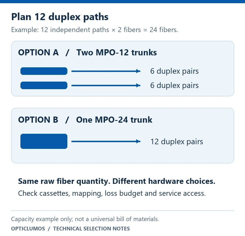
Suppose a rack design needs twelve independent two-fiber paths. Its raw fiber requirement is 12 × 2 = 24 fibers. Two fully populated MPO-12 trunks or one fully populated MPO-24 trunk can provide that quantity. This arithmetic is a planning example, not a universal bill of materials.
- Check panel compatibility: available cassettes, adapters, harnesses and spare ports may determine the practical choice.
- Define failure and maintenance boundaries: identify how many circuits are disturbed when a shared trunk is disconnected.
- Allow for growth deliberately: reserve labeled fibers or additional pathways rather than leaving unknown spare positions.
- Count every connection: a more compact route can still introduce extra mated pairs through conversion hardware.
A 24-fiber backbone can also be divided into multiple eight-fiber paths using purpose-designed conversion components. Fluke’s MPO data-center guide discusses such aggregation. Require an explicit transition map and test all resulting channels; a passive adapter does not itself provide arbitrary fiber remapping.
Five checks that fiber count cannot replace
- Interface: record the actual equipment and cassette part numbers, connector format, key reference and polish.
- Pinning: specify male or female at every mating point. Use the MPO male/female checklist.
- Continuity: approve a position-to-position map across the complete route. Refer to the 12-fiber polarity guide, without extending its drawing to 24 fibers by assumption.
- Optical budget: allocate fiber attenuation and connector/splice losses against the exact application’s permitted channel loss.
- Acceptance: retain per-fiber measurements and mapping results. Our insertion loss and return loss guide explains the distinction between these tests.
What to include in an MPO trunk RFQ
Send one interface schedule with the quotation request. It should specify both endpoints, fiber type, ferrule format, populated positions, cable and branch lengths, allowable tolerances, jacket requirements, labels and quantity. Attach the full route map if the assembly passes through a panel or cassette.
State the test wavelength, reference method, maximum loss per fiber, required return-loss testing where applicable, and report format. Identify whether unallocated fibers also require acceptance testing. Preserve the approved drawing revision so repeat orders reproduce the intended assembly.
Frequently asked questions
Is MPO-24 faster than MPO-12?
No. Fiber count describes physical capacity. The optical application, lane rate, equipment and channel performance determine supported data rates.
Can a 12-fiber trunk be used for an eight-fiber SR4 link?
It can, when its populated positions and all interface, mapping, fiber and loss requirements match the equipment. The extra four positions do not become additional active SR4 lanes.
Can I mate MPO-24 directly to MPO-12?
Do not assume compatibility from the MPO name or outer appearance. Specify the ferrule geometry and an approved transition component where needed.
Do more fibers guarantee an upgrade path?
No. A future module may require a different ferrule, fiber grade, polish or lane map. Plan against named future interfaces and documented component compatibility.
Specify the MPO assembly around your equipment
Review our MPO connector and cable assembly options, then send your interface drawing, fiber population and channel map for a technical quotation.
View MPO assemblies Request a technical quote