
Short answer: A useful custom passive optical component specification defines function, operating wavelength, port configuration, insertion loss, return loss, polarization behavior, power, connector or fiber interface, environment and acceptance testing. Start with the optical system requirement—not a supplier part number—and request a controlled drawing plus measured results for the delivered configuration.
What is a passive optical component?
A passive optical component routes, divides, combines, filters, couples or connects optical signals without adding optical gain. Common families include couplers, splitters, wavelength-selective devices, isolators, circulators, filters, connectors, PM jumpers and custom fiber assemblies. Some devices use magneto-optic materials or complex packaging, but they remain passive because the optical function does not require electrical amplification.
The phrase custom fiber optic component can describe a modified wavelength, coupling ratio, fiber type, port layout, connector, jacket, package or test requirement. It does not imply that every parameter can be changed independently. A manufacturer must review optical, mechanical and environmental tradeoffs as one configuration.
Passive optical component types and functions
| Component family | Primary function | Important RFQ parameters |
|---|---|---|
| Fiber coupler or splitter | Divide or combine optical power | Wavelength, coupling ratio, port count, excess loss, uniformity and directivity |
| WDM device or filter | Combine, separate or pass selected wavelength bands | Passband, isolation, insertion loss, ripple, channel spacing and temperature |
| Isolator | Reduce backward-propagating light | Wavelength, isolation, insertion loss, return loss, power and polarization dependence |
| Circulator | Route light sequentially between ports | Port direction, insertion loss, isolation, crosstalk, wavelength and power |
| Connectorized jumper | Provide a repeatable fiber interface | Fiber type, connector, polish, key orientation, loss, return loss and length |
| PM component or assembly | Maintain or control a defined polarization axis | Operating axis, wavelength, PER, crosstalk, connector key, launch and bend condition |
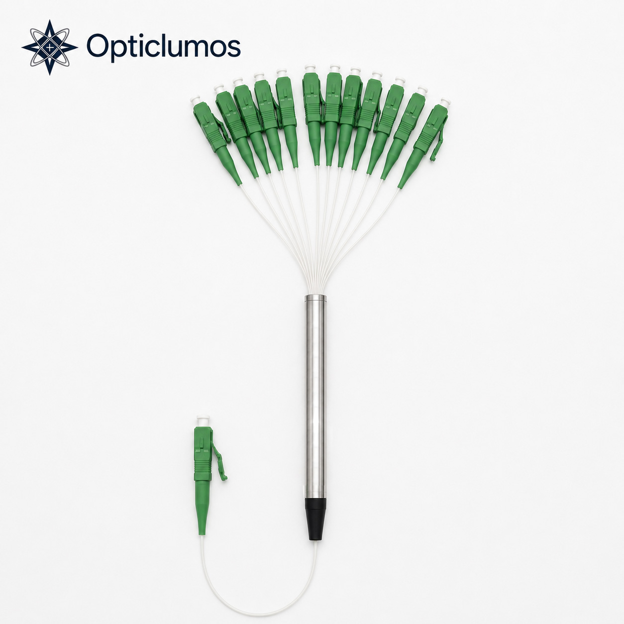
| Fiber bundle or breakout assembly | Organize multiple optical channels | Fiber count, channel map, fan-out, connectors, labeling, length and inspection |
Eight specifications buyers should define
- Operating wavelength or spectral band: insertion loss and coupling behavior are wavelength-dependent. State the source wavelength and tolerance.
- Optical function and port map: provide the required input/output relationship, port numbering and propagation direction.
- Insertion loss: state whether the limit applies per path, per connector or end-to-end, and identify the test wavelength.
- Return loss or reflectance: reflection-sensitive lasers, interferometers and sensors often need stricter control than ordinary links.
- Polarization behavior: specify PDL for non-PM devices or axis, PER/crosstalk and test method for PM configurations.
- Optical power: provide average and peak power, pulse duration, repetition rate and beam conditions where applicable.
- Mechanical interface: define bare fiber or connector, polish, pigtail length, jacket, package dimensions and mounting needs.
- Environment and reliability: include operating/storage temperature, humidity, vibration, shock, sealing and qualification requirements relevant to the installation.
Insertion loss, return loss, PDL and directivity are not interchangeable
| Metric | What it describes | Common purchasing mistake |
|---|---|---|
| Insertion loss (dB) | Optical power lost through a specified path | Not defining wavelength, direction or whether connectors are included |
| Return loss (dB) | Ratio describing reflected power; a higher positive dB value generally means less reflection | Confusing return loss with insertion loss |
| PDL (dB) | Change in insertion loss as input polarization changes | Using PDL as a substitute for PM assembly PER |
| Directivity/isolation (dB) | Unwanted coupling or reverse transmission between defined ports | Comparing values without the same port pair and wavelength |
| PER (dB) | Power ratio between orthogonal polarization components under a defined measurement setup | Assuming fiber crosstalk guarantees finished connectorized assembly PER |
For polarization-sensitive projects, review the polarization extinction ratio measurement guide and the Panda PM fiber jumper specifications.
A practical component-selection workflow
- Describe the system function: state what the component must do and where it sits in the optical path.
- Identify mandatory interfaces: list source, detector, fiber type, connector, mating adapter and available package space.
- Separate target from limit: distinguish a preferred nominal value from a pass/fail acceptance criterion.
- Define a reference path: number ports and provide a small diagram so that loss, isolation and direction are unambiguous.
- Review environmental conditions: add temperature and mechanical requirements that can change packaging or fiber choice.
- Approve a drawing and test plan: confirm revision, tolerances, labels and recorded measurements before production.
What should an acceptance test report contain?
The report should match the approved configuration and identify the device or assembly, test date, wavelength, equipment or method, port path and pass/fail limits. Depending on the product, records may include insertion loss, return loss, isolation/directivity, coupling ratio, PDL, PER, end-face inspection and continuity/channel mapping.
Do not request every possible test by default. Select tests that control the actual risk. A connectorized telecom splitter and a PM interferometric assembly do not need identical documentation. International references such as ITU-T G.671 and the IEC 61300 series provide terminology and test-method frameworks, but the purchase drawing must still define the applicable values.
How to evaluate a custom fiber optic component manufacturer
- Application review: can the supplier identify incompatible wavelength, power or interface requirements before quoting?
- Drawing control: are ports, fibers, connectors, dimensions and revision status clearly documented?
- Traceable inspection: are test results associated with the delivered configuration or production batch?
- Prototype-to-production control: are changes in materials or process reflected in the approved specification?
- Communication: can technical questions be resolved with evidence instead of generic maximum-performance claims?
Use the Opticlumos optical components and connectors page to compare available product families. For multi-channel routing, see the custom fiber optic bundle selection guide.
RFQ checklist for custom passive optical components
- Component function and port diagram
- Operating wavelength, bandwidth and source type
- Fiber type, operating axis and jacket
- Connector family, polish, keying and pigtail length
- Insertion-loss and return-loss limits by path
- Coupling ratio, uniformity, isolation, PDL or PER where applicable
- Average/peak power and pulse conditions
- Operating/storage environment and package dimensions
- Required inspection records and acceptance method
- Prototype and production quantity
RFQ example
“Please review a 2×2 PM fiber coupler for 1550 nm. Define the required coupling ratio tolerance, insertion loss, return loss, PER/crosstalk test method, Panda fiber pigtails, FC/APC key orientation, 1 m pigtail length and operating temperature. Quote five prototypes and the production quantity.”
Send a port diagram or drawing with the checklist above through the technical inquiry form. Final availability and limits are confirmed after configuration review.
Frequently asked questions
What is the difference between an active and passive optical component?
An active component requires electrical power to generate, detect, amplify or actively control a signal. A passive component routes, divides, filters, couples or connects light without optical gain.
Does lower insertion loss always mean a better component?
No. Loss matters, but the component must also meet isolation, bandwidth, power, polarization, environmental and interface requirements. A single best number rarely describes system suitability.
Should connector loss be included in the component limit?
The RFQ should state this explicitly. Define whether acceptance is for the internal device, each connector, or the complete end-to-end assembly.
Can a standard coupler be used in a PM system?
Only if its polarization behavior and interfaces meet the system requirement. PM systems normally require controlled fiber axes, key orientation, launch conditions and a defined PER or crosstalk test.
What information speeds up a custom quotation?
A port diagram, wavelength, fiber and connector details, optical limits, environment, quantity and required test report allow the fastest technical review.
Technical reference
- ITU-T G.671 — Transmission characteristics of optical components and subsystems
- IEC 61300 series — Fibre optic interconnecting devices and passive components: basic test and measurement procedures.