
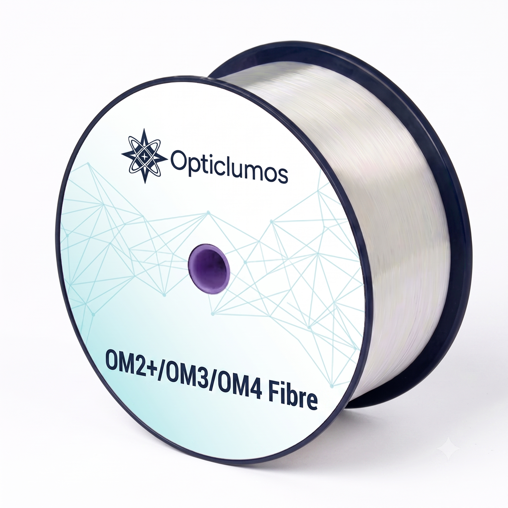
MaxBand® OM2+ / OM3 / OM4 Bending Insensitive Multimode Fibre
Key Features & Target Applications
Advanced Optical Features
- ✔ Optimized for 850nm VCSEL transmission
- ✔ Low differential mode delay (DMD)
- ✔ High bandwidth and remarkably low attenuation
- ✔ Superior geometry uniformity
- ✔ Very low macro-bending sensitivity for small bending radii
- ✔ Coated with YOFC's proprietary dual layer UV curable acrylate
- ✔ Full compatibility with current OM2+/OM3/OM4 multimode networks
Ideal Network Applications
- ✔ Next-generation Data Centers & Data storage networks
- ✔ High-performance computing centers (HPC)
- ✔ 1, 10, 40, 100, and 400 Gb/s Ethernet deployments
- ✔ Local area networks (LAN) and Office centers
- ✔ Optimized performance in tight-buffer cable applications
- ✔ Environments requiring high resistance to micro-bending
Global Standards Compliance
The YOFC MaxBand® OM2+/OM3/OM4 Bending Insensitive Multimode Fibres strictly comply with or exceed the highest international specifications:
- ISO/IEC 11801-1 OM2/OM3/OM4 specifications
- IEC 60793-2-10 A1-OM2 / A1-OM3 / A1-OM4 specifications
- TIA-492AAAF A1-OM2 / A1-OM3 / A1-OM4 specifications
System Link Length Support
Maximum supported link distances based on Ethernet speeds and fiber classifications.
| Fibre Type | 10 Gb/s Link Length (@850nm) | 40 & 100 Gb/s Link Length (@850nm) |
|---|---|---|
| MaxBand OM4 Bending Insensitive Fibre | 550 meters | 170 meters |
| MaxBand OM3 Bending Insensitive Fibre | 300 meters | 140 meters |
| MaxBand OM2+ Bending Insensitive Fibre | 150 meters | - |
Comprehensive Technical Specifications
Below are the precise technical parameters defining the geometry, optical properties, environmental resilience, and mechanical strength of the product series.
| Characteristics | Conditions | Specified Values (OM2+/OM3/OM4) | Units |
|---|---|---|---|
| Geometry Characteristics | |||
| Core Diameter | - | 50 ± 2.5 | µm |
| Core Non-Circularity | - | ≤ 5.0 | % |
| Cladding Diameter | - | 125.0 ± 1.0 | µm |
| Cladding Non-Circularity | - | ≤ 0.6 | % |
| Coating Diameter | - | 245 ± 7 | µm |
| Coating/Cladding Concentricity Error | - | ≤ 10.0 | µm |
| Coating Non-Circularity | - | ≤ 6.0 | % |
| Core/Cladding Concentricity Error | - | ≤ 1.0 | µm |
| Delivery Length | - | up to 8.8 | km/reel |
| Optical Characteristics | |||
| Attenuation | 850nm 1300nm |
≤ 2.4 ≤ 0.6 |
dB/km dB/km |
| Overfilled Modal Bandwidth | 850nm 1300nm |
≥ 700 / 1500 / 3500 ≥ 500 / ≥ 500 / ≥ 500 |
MHz·km MHz·km |
| Effective Modal Bandwidth | 850nm | ≥ 950 / ≥ 2000 / ≥ 4700 | MHz·km |
| Application support distance on 40GBASE-SR4/100GBASE-SR10 | 850nm | - / 140 / 170 | m |
| 10GBASE-SR | 850nm | 150 / 300 / 550 | m |
| 1000BASE-SR | 850nm | 750 / 1000 / 1100 | m |
| DMD Specification | Compliant with and more stringent than the requirements of IEC 60793-2-10 | ||
| Numerical Aperture | - | 0.200 ± 0.015 | - |
| Group Refractive Index | 850nm 1300nm |
1.482 1.477 |
- |
| Zero Dispersion Wavelength, $\lambda_{0}$ | - | 1295 - 1340 | nm |
| Zero Dispersion Slope, $S_{0}$ | $1295\text{ nm} \le \lambda_{0} \le 1310\text{ nm}$ $1310\text{ nm} \le \lambda_{0} \le 1340\text{ nm}$ |
≤ 0.105 ≤ 0.000375 (1590 - $\lambda_{0}$) |
ps/(nm²·km) ps/(nm²·km) |
| Macrobending Loss (2 Turns @ 15 mm Radius) |
850nm 1300nm |
≤ 0.1 ≤ 0.3 |
dB dB |
| Macrobending Loss (2 Turns @ 7.5 mm Radius) |
850nm 1300nm |
≤ 0.2 ≤ 0.5 |
dB dB |
| Backscatter Characteristics (1300nm) | |||
| Step (Mean of Bidirectional Measurement) | - | ≤ 0.10 | dB |
| Irregularities Over Fibre Length and Point Discontinuity | - | ≤ 0.10 | dB |
| Attenuation Uniformity | - | ≤ 0.08 | dB/km |
| Environmental Characteristics (850nm & 1300nm) | |||
| Temperature Cycling | -60°C to 85°C | ≤ 0.10 | dB/km |
| Temperature-Humidity Cycling | -10°C to 85°C, 4% to 98% RH | ≤ 0.10 | dB/km |
| Water Immersion | 23°C, 30 days | ≤ 0.10 | dB/km |
| Dry Heat | 85°C, 30 days | ≤ 0.10 | dB/km |
| Damp Heat | 85°C, 85% RH, 30 days | ≤ 0.10 | dB/km |
| Mechanical Specification | |||
| Proof Test | - | ≥ 9.0 ≥ 1.0 ≥ 100 |
N % kpsi |
| Coating Strip Force | Typical average force Peak force |
1.5 ≥ 1.3, ≤8.9 |
N N |
| Dynamic Stress Corrosion Susceptibility Parameter ($n_{d}$ typical) | - | 20 | - |
*Remarks: 1. Support distances considering maximum cable attenuation of 3.0 dB/km at 850 nm, maximum total splice/connector loss of 1.0 dB and VCSELs maximum RMS spectral width ≤0.45 nm. 2. The launch condition for the macrobending loss measurement fulfils that described in IEC 61280-4-1.
OM3/OM4 Multimode Fiber Buyer Guide
MaxBand® OM3 and OM4 multimode fibers are optimized for high-speed short-reach links using 850 nm VCSEL transmission. Typical projects include data centers, enterprise backbones, high-performance computing and structured cabling systems.
Information to Include in Your RFQ
- OM3 or OM4 grade and applicable network standard
- Data rate, wavelength and required link distance
- Fiber/cable construction, connector interface and test requirements
- Order length, packaging, quantity and destination
Frequently Asked Questions
How should I choose between OM3 and OM4?
Choose according to the required data rate, link distance, transceiver specification and cabling standard. OM4 is normally selected when the design requires greater bandwidth margin or longer supported reach.
Are OM3 and OM4 designed for 850 nm VCSEL systems?
Yes. They are laser-optimized multimode fiber grades commonly used with 850 nm VCSEL-based transmission systems.
What transmission distance can be supported?
Supported reach depends on Ethernet or Fibre Channel standard, data rate, transceiver, connector loss and overall link budget. Provide the complete system requirement for confirmation.
Technical inquiry: sales@opticlumos.com · WhatsApp +86 13871596508