
High-Voltage Power Valve Optical Fiber
Wide-core polymer-clad optical fiber for transmitting trigger light or control energy inside high-voltage power valve systems. Available in several core, numerical-aperture and coating configurations for project-specific coupling and routing requirements.
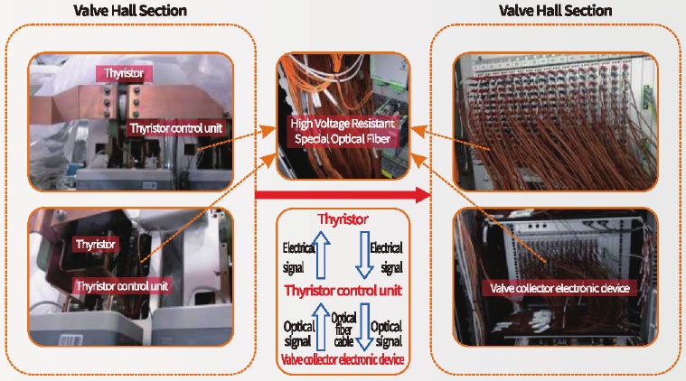
Why This Fiber Is Used in Power Valve Triggering
Wide-Core Coupling
Reference designs use core diameters from 62.5 µm to 200 µm to support efficient coupling from the selected trigger-light source.
Electrical Isolation
The optical path transmits a control signal without providing an electrical conduction path and is resistant to electromagnetic interference.
Polymer-Clad Protection
PVDF-based rigid plastic cladding is used to improve moisture resistance, tensile strength and handling robustness compared with conventional glass-clad constructions.
Reference Optical Fiber Specifications
| Fiber type | Core / cladding / coating (µm) | NA | Attenuation @850 nm | Index profile |
|---|---|---|---|---|
| GIMMF62.5/125-27/250 | 62.5±2.5 / 125±1.0 / 245±7 | 0.27±0.02 | ≤2.7 dB/km | Graded index |
| SIMMF105/125-22/250 | 105±3 / 125±2 / 250±20 | 0.22±0.02 | ≤3.0 dB/km | Step index |
| SIMMF200/240-20/375 | 200±3 / 240 +0/-8 / 375 (500)±25 | 0.20±0.02 | ≤6.0 dB/km | Step index |
| HP-MMC200/230-37/500E | 200±3 / 230 +0/-8 / 500±30 | 0.37±0.02 | ≤8.0 dB/km | Step index |
| Characteristic | 62.5/125 | 105/125 | 200/240 | 200/230 |
|---|---|---|---|---|
| Short-term bend radius | ≥10 mm | ≥30 mm | ≥30 mm | ≥10 mm |
| Long-term bend radius | ≥16 mm | ≥50 mm | ≥50 mm | ≥16 mm |
| Proof-test tension | 100 kpsi | |||
| Operating temperature | -55 to +85°C | |||
Configuration note: these are catalog reference values, not a substitute for a final approved drawing. Confirm the light source, coupling optics, fiber length, routing, termination, temperature and acceptance test before production. ETT and LTT application references in the source catalog indicate electric-control-valve and light-control-valve solutions.
Selection Inputs
- Trigger-light source wavelength, power, spot size and numerical aperture
- Required core, cladding, coating and overall protected diameter
- Fiber length, route, allowable short- and long-term bend radius
- Continuous/peak temperature, moisture, dust and chemical exposure
- End preparation, ferrule or connector, polish and coupling interface
- Attenuation, transmitted-power and acceptance-test requirements
- Quantity, labeling, packaging and valve-hall installation constraints
Applications
Frequently Asked Questions
Is this the same as standard telecom multimode fiber?
No. The catalog configurations include wide-core step-index and graded-index fibers intended for trigger-light coupling and industrial power-valve use. Select by the actual light source and interface.
Which core diameter should I choose?
Choose from the source size, focused spot, numerical aperture, coupling tolerance and required routed diameter. A larger core does not automatically guarantee better system efficiency.
Can the fiber be supplied as a finished assembly?
End preparation and protective construction can be reviewed against drawings. Provide the mating interface, length, routing and acceptance requirements.
Is the fiber immune to all high-voltage effects?
The optical path is dielectric and resistant to electromagnetic interference, but the finished installation still requires electrical clearances, material review and project-specific qualification.
Related Products & Guides
Specify a Power Valve Fiber
Send the source wavelength and NA, core size, fiber length, routing, termination, environment and acceptance test for engineering review and quotation.