
An MPO-to-LC breakout cable distributes a multifiber MPO interface into individual LC terminations. The useful specification is a channel map with dimensions, not just “MPO to LC” and a cable length.
1. Separate duplex distribution from parallel-optics breakout
| Use case | What the harness does | What must be confirmed |
|---|---|---|
| Duplex LC distribution | Routes populated MPO positions to separate LC terminations or duplex pairs | Each pair’s transmitter/receiver path, cassette map and port labels |
| Parallel-optics equipment breakout | Routes optical lanes from a compatible MPO interface to individual connections | Transceiver lane assignment, compatible remote optics and host breakout support |
| Custom equipment interconnect | Implements a project-specific multifiber-to-single-fiber map | Electrical/optical system design, fiber identities and acceptance drawing |
A 12-fiber harness can provide twelve simplex LC terminations or six duplex pairs when all positions are used in that arrangement. This arithmetic does not prove it is the correct harness for a parallel-optics transceiver. For example, some SR4 architectures use eight active fibers within a 12-position interface. Follow the equipment’s actual transmit and receive positions rather than assigning adjacent positions by habit.
For background, Fluke Networks explains base-8 and base-12 connectivity. Cable selection must remain specific to the equipment; a harness alone does not make a 100G port operate as an arbitrary set of lower-speed links.
2. Approve the fiber-to-port map
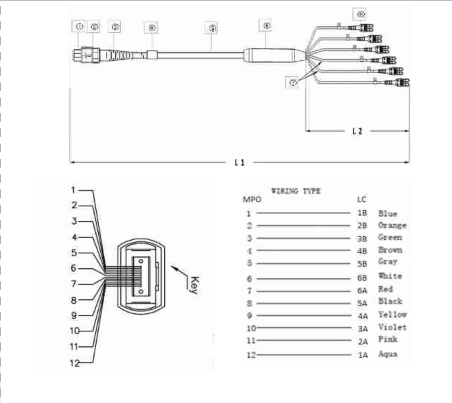
Number the MPO positions using the drawing’s stated viewing direction and key orientation. Identify whether the drawing shows the mating face or the cable side. Then list the LC termination attached to each populated position and the intended remote port. Photographs and jacket colors cannot replace this record.
| MPO position | LC label | Project-assigned role | Acceptance record |
|---|---|---|---|
| 1 | L01 | Record equipment lane/port | Continuity and loss result for L01 |
| 2 | L02 | Record equipment lane/port | Continuity and loss result for L02 |
| 3–11 | L03–L11 | List each channel separately in the production drawing | One result for every specified channel |
| 12 | L12 | Record equipment lane/port | Continuity and loss result for L12 |
This is an illustrative identity-label schedule, not an SR4 wiring recommendation. Assign duplex pairs only after checking the full system map. In the RFQ, state whether LC connectors are simplex or clipped into duplex pairs and whether paired legs must remain together during installation.
Need the position-by-position map? Use the 12-fiber MPO polarity A, B and C guide to compare cable maps and verify the complete channel before specifying a breakout.
3. Keep polarity, gender and polish separate
Polarity describes routing. For conventional 12-fiber MPO trunks, Type A preserves positions, Type B reverses the order and Type C swaps adjacent pairs. These trunk descriptions do not fully describe a harness plus adapters, cassettes and patch cords. See Fluke Networks’ polarity explanation.
Gender describes pins. Male MPO connectors have alignment pins; female connectors do not. Record the actual mating interface and specify the corresponding cable end. Do not infer pinning from “Type B” or from fiber count.
For a mating-pair checklist and ordering examples, see our MPO male vs female connector guide.
Polish describes the endface. Match the required PC/UPC or APC interface at each connection. Confirm keying and adapter arrangements for the selected system rather than applying a generic key-up rule to every APC link. Our MTP vs MPO comparison separates these compatibility checks from connector branding.
4. Specify branch protection and finished lengths
Record overall length, the measurement reference points, breakout position and every leg length. Equal legs simplify an order but may create unnecessary slack across a row of ports. Staggered lengths can suit a fixed port layout, provided both the port map and installation direction are frozen.
| Drawing option | Review before choosing | Dimensions to identify |
|---|---|---|
| 0.9 mm fanout format | Protection inside the intended enclosure and handling at the breakout | Exposed leg lengths and the protected routing path |
| 2.0 mm fanout format | Branch routing, strain relief and port clearance | Each branch length, breakout position and boot clearance |
| 3.0 mm cable fanout format | Available tray/enclosure space and the exact cable/branch construction | All diameters separately labeled on the assembly drawing |
These are available drawing formats, not universal mechanical ratings. Confirm minimum bend radius, tensile limits, jacket requirements and environmental conditions for the selected construction. The broader breakout vs fan-out vs pigtail guide explains assembly terminology.
5. Define acceptance before ordering
- Verify dimensions, connector identification, pinning and labels against the approved drawing.
- Inspect the mating faces; clean and reinspect as required using a suitable procedure.
- Check continuity and polarity for every populated position, including unused-by-the-application fibers if specified for delivery.
- Measure insertion loss under agreed wavelengths and reference conditions. Record each channel rather than only an assembly average.
- Check the completed channel budget and equipment operation after installation. Factory cable results do not replace the final link check.
Distinguish maximum connector loss from total harness or channel loss. Include every mated connection, fiber attenuation and other passive elements when comparing against the equipment budget. See our optical loss-budget guide.
Before setting acceptance limits, use our insertion loss vs return loss guide to distinguish transmitted power, reflected power and per-fiber MPO test results.
RFQ checklist for an MPO-to-LC harness
Copy and complete: equipment and link purpose; MPO layout and populated positions; SM/MM and fiber grade; MPO pinning and polish; LC polish and simplex/duplex arrangement; position-to-LC map; total length and reference points; branch lengths and diameters; jacket and environment; per-channel optical limits and test conditions; labels; quantity; required delivery documentation.
Frequently asked questions
Is an MPO-to-LC cable the same as an MPO trunk?
No. A trunk has multifiber terminations at both ends. An MPO-to-LC harness distributes the MPO positions to individual LC terminations.
Does a 12-fiber harness always mean six duplex ports?
Only if the approved mapping uses all twelve fibers as six duplex pairs. Parallel-optics lane assignments may require a different pairing or fewer active positions.
Can I order using Type B alone?
That is incomplete. Also specify the pinning, polish, populated positions, LC pairing, dimensions and complete equipment-to-equipment map.
Does the cable convert speed or protocol?
No. It is a passive optical routing assembly. Both transceivers and the host configuration must support the intended breakout arrangement.
Get an MPO-to-LC drawing and quote
Send the equipment interface, LC port map and branch dimensions. OpticLumos can review the configuration before quoting the assembly.