
MPO Fiber Optic Connector & Cable Assemblies
Connect multiple optical fibers through one compact interface. OpticLumos supplies configurable MPO trunk patch cords and MPO-to-LC fanout assemblies for data-center racks, high-density patching and compatible parallel optical links.
4 / 8 / 12 / 24 fibers · Single-mode or multimode · Type A or B mapping
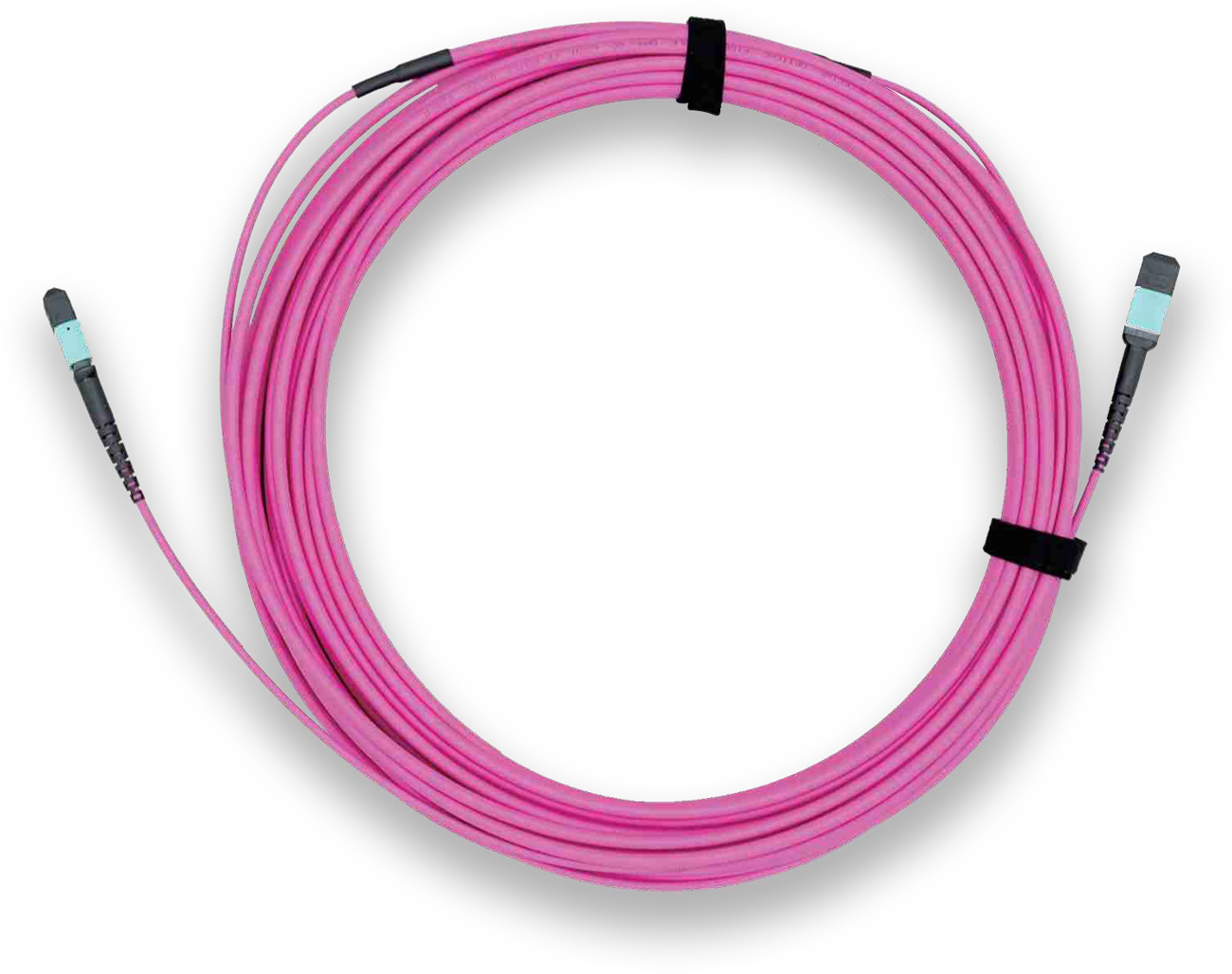
Choose the MPO Assembly for Your Link
MPO-to-MPO Trunk
A multi-fiber connection between compatible panels, cassettes or equipment. Specify the fiber layout, male/female ends, polarity and total cable length.
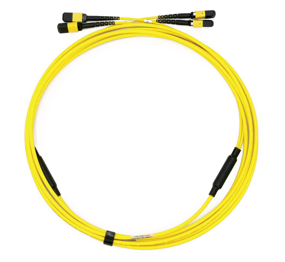
MPO-to-LC Fanout
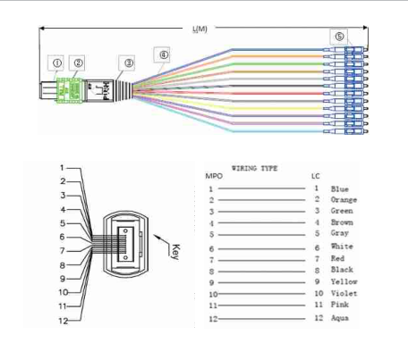
Distribute one MPO interface into individual LC terminations. Define branch protection, fanout length, port numbering and the channel map.
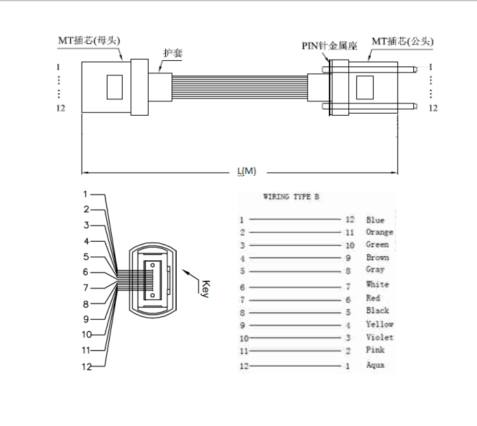
MT-to-MT Ribbon
A ribbon-fiber termination configuration for integration into equipment. The ferrule, pin layout and protective enclosure need to match the system drawing.
MPO Connector Optical Performance
| Parameter | Single-mode (SM) | Multimode (MM) |
|---|---|---|
| Insertion loss, low-loss grade | ≤0.35 dB | ≤0.30 dB |
| Insertion loss, standard grade | ≤0.75 dB | ≤0.70 dB |
| Return loss, PC | ≥50 dB | ≥25 dB |
| Return loss, APC | ≥60 dB | Confirm for the selected configuration |
| Loss change after 500 mating/unmating cycles | <0.3 dB | <0.3 dB |
Select the optical grade and polish explicitly. Confirm the test wavelength, reference method and per-channel acceptance criteria in the order; connector performance values are not the total loss budget of a completed channel.
Configuration & Ordering Options
| Selection | Options / information to specify |
|---|---|
| Fiber count | 4, 8, 12 or 24; confirm ferrule layout and populated positions |
| Fiber type | G.652 or G.657A single-mode; 50/125 or 62.5/125 multimode; OM2, OM3 and OM4 options |
| MPO ends | Male or female at each end; PC or APC endface as applicable |
| Assembly type | MPO trunk, MT ribbon jumper, or fanout to LC / SC / FC |
| Polarity | Type A straight-through or Type B reversed mapping; approve the complete channel map |
| Fanout construction | MPO-to-LC examples in 0.9 mm, 2.0 mm and 3.0 mm formats |
| Dimensions | Total length, breakout position, branch lengths, jacket and routing constraints |
| Documentation | Approved assembly drawing, channel identification and agreed optical test results |
For projects specifying IEC 61754-7 interfaces or RoHS requirements, identify the applicable requirements and required documentation in the RFQ so the selected configuration can be confirmed.
MPO Product Images
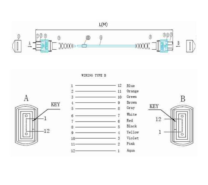
Original Assembly Drawings & Channel Mapping
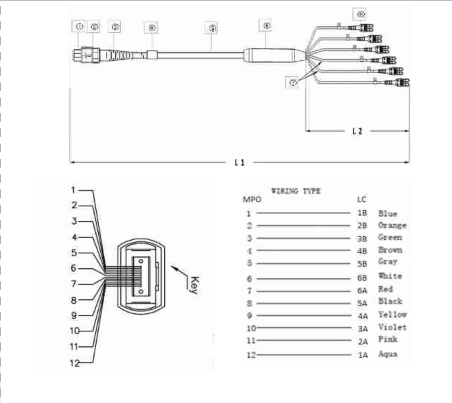
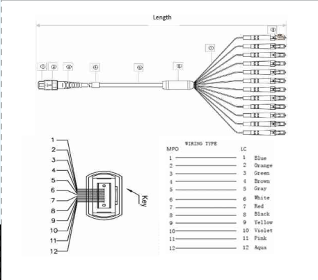
Use these reference structures to identify the required assembly. The approved production drawing should define connector orientation, pin configuration, channel map and all finished lengths.
MPO-to-MPO 3.0 mm Trunk
MT-to-MT Ribbon Jumper
MPO-to-LC 0.9 mm Fanout
MPO-to-LC 2.0 mm Fanout
MPO-to-LC 3.0 mm Cable Fanout
Polarity, Pinning & Link Compatibility
- Identify both interfaces. Record the equipment or cassette connection and its required pinned/unpinned configuration.
- Approve the channel map. Confirm Type A or B with the adapters and end equipment. A cable’s polarity letter does not describe the complete link.
- Match fiber and polish. Specify SM or MM, the required fiber grade, and PC/APC endfaces. Do not assume matching connector colors prove compatibility.
- Check the optical budget. Include connector pairs, fiber attenuation and other channel components. Choose standard or low-loss grade accordingly.
- Inspect and test. Inspect and clean the mating endfaces; verify continuity, polarity and loss for every specified channel before service.
Background on complete-link polarity: Fluke Networks’ 12-fiber MPO polarity guide.
Applications
Match the assembly to the transceiver specification and channel design. Interface density alone does not establish supported reach or transmission speed.
Frequently Asked Questions
What is an MPO fiber connector?
MPO stands for Multi-fiber Push On. It aligns several fibers in a single connector interface, making it useful for compact patching, trunk connections and parallel optical links.
Which fiber counts can I specify?
Ordering options include 4, 8, 12 and 24 fibers. Confirm the populated positions, ferrule layout and end-to-end channel map, rather than selecting by fiber count alone.
What is the difference between male and female MPO connectors?
Male connectors have alignment pins; female connectors have matching guide holes. Specify the pin configuration at both ends and check the equipment or cassette interface before ordering.
Should I choose Type A or Type B polarity?
Type A uses a straight-through mapping. In the illustrated 12-fiber Type B assembly, position 1 maps to 12, 2 to 11, and so on. Select polarity for the complete link, including adapters, cassettes and transceiver Tx/Rx mapping.
Can you supply an MPO to LC fanout cable?
MPO-to-LC fanout configurations include 0.9 mm, 2.0 mm and 3.0 mm construction examples. Specify the total length, fanout length, LC port order, fiber type and connector polish.
Is every MPO connector an MTP connector?
No. MTP is a US Conec brand of MPO connector. This page specifies MPO assemblies; any requirement for a particular connector brand or part number must be stated and confirmed in the quotation.
Does an MPO interface guarantee 40G or 100G operation?
No. MPO assemblies can be used in compatible 40G and 100G cabling designs, but the transceiver interface, fiber type, number of active fibers, reach, polarity and total link-loss budget determine suitability.
Related Products & Selection Guides
- MPO polarity A, B and C: check the 12-fiber channel map
- MPO male vs female: confirm pins and mating pairs
- Insertion loss vs return loss: define per-fiber acceptance tests
Plan your connection with our MTP vs MPO compatibility guide and MPO-to-LC breakout cable selection guide.
- Optical Components & Connectors
- Custom Fiber Optic Fan-Out Cable Assemblies
- Fiber Optic Bundle & Ribbon Cable Assemblies
MTP® is a US Conec brand of MPO connector. Brand-specific components must be separately confirmed; see US Conec’s MTP connector information.
Get a Quote for Your MPO Assembly
Send fiber count and type, connector gender at both ends, PC/APC polish, polarity map, total and fanout lengths, loss grade, quantity and required test documentation.
RFQ example: 12-fiber OM4 MPO-to-MPO, female/female, Type B, 3.0 mm cable, 5 m, low-loss MM grade ≤0.30 dB; confirm interface polish and channel test conditions.