
MPO polarity is the end-to-end fiber map that connects each transmitter to its intended receiver. A correct connector fit does not prove that the optical lanes are connected correctly.
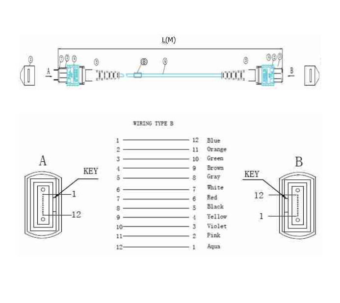
MPO polarity A, B and C: 12-fiber position maps
The table is a logical continuity schedule from End A to End B. It is not a connector mating-face drawing: both faces need an explicit viewing direction and position-1 reference on the production drawing.
| Position at End A | Type A: End B | Type B: End B | Type C: End B |
|---|---|---|---|
| 1 | 1 | 12 | 2 |
| 2 | 2 | 11 | 1 |
| 3 | 3 | 10 | 4 |
| 4 | 4 | 9 | 3 |
| 5 | 5 | 8 | 6 |
| 6 | 6 | 7 | 5 |
| 7 | 7 | 6 | 8 |
| 8 | 8 | 5 | 7 |
| 9 | 9 | 4 | 10 |
| 10 | 10 | 3 | 9 |
| 11 | 11 | 2 | 12 |
| 12 | 12 | 1 | 11 |
Read one row at a time: position 1 reaches 1 in A, 12 in B and 2 in C. Do not use jacket color to infer the map. Fluke Networks provides the technical background on MPO connectivity and polarity.
A cable type is not the complete polarity method
Picture a channel as equipment A → patch lead → cassette → trunk → cassette → patch lead → equipment B. Each component can change which fiber arrives at the next interface. Reading only the trunk label leaves the rest of that route unspecified.
For a duplex LC distribution system, document the two fibers assigned to each equipment port and trace both directions. For parallel optics, document the individual transmit and receive lanes from the transceiver datasheet. Do not assume that every adjacent pair is a duplex circuit.
Some SR4 systems use eight active fibers in a twelve-position interface. The occupied positions and lane assignments must match the specific optics. A 12-position shell does not mean twelve active lanes, and the map above must not be extrapolated to 16- or 24-fiber interfaces.
Fluke’s 12- and 8-fiber polarity guidance explains why channel architecture matters. Type C pair swapping can serve duplex distribution; it is not a universal direct connection for parallel optics.
If your assembly ends in LC connectors, use our MPO-to-LC breakout selection guide for branch dimensions and port labels. For brand terminology and interface compatibility, see MTP versus MPO connectors.
Keep polarity, pinning, keying and polish separate
| Specification | Question to resolve | Record in the drawing |
|---|---|---|
| Polarity | Where does each fiber go? | End-to-end position and equipment-lane schedule |
| Pinning | Which side provides the alignment pins? | Pinned or unpinned at each mating interface |
| Key orientation | How are the two connector faces oriented? | Key direction and adapter configuration |
| Polish | Are the mating end faces compatible? | Specified PC/UPC or APC interface at each end |
| Fiber grade | Does the medium match the optical system? | Single-mode or the required multimode grade |
Pinning is a mechanical alignment choice; it does not identify the fiber map. Likewise, a familiar key arrangement is insufficient when adapters or internal cassette routing differ. APC end-face alignment deserves explicit review; do not copy a key-up/key-up recipe from a different polish configuration. Confirm the complete connector and adapter combination with the component supplier.
A practical verification workflow
Freeze the equipment interfaces
Record exact transceiver or module part numbers, port functions and the planned channel. Ask the equipment owner to approve the lane assignment before choosing a trunk.
Make a connection schedule
Give each cable and intermediate component an identifier. Trace every required source position to its destination, including cassette ports and LC pair labels. Resolve empty positions explicitly.
Check the delivered assembly
Compare labels, drawing revision, lengths and connector configuration with the purchase order. Quarantine discrepancies before they become installation changes.
Measure mapping and optical loss
Use an appropriate multifiber tester or a documented per-fiber procedure. Preserve individual channel results rather than only a single pass mark. Specify test wavelength, reference method, limits and report identifiers in the acceptance plan.
Verify after installation
Confirm the installed route matches the approved schedule. If a link fails, compare the as-built component sequence with the drawing before replacing parts or changing polarity at random.
Correct continuity and acceptable insertion loss answer different questions. A mapped fiber can still have excessive loss; low loss measured on an unintended route does not establish a correct transmitter-to-receiver connection.
What to send for an MPO polarity quotation
- Equipment part numbers, link architecture and required optical lanes.
- Fiber grade, number of populated positions and intended spare positions.
- Connector family, pinning, polish and key/viewing references at each end.
- Position-to-position map, or MPO-position-to-LC-port schedule.
- Trunk and branch lengths, tolerances, labels and installation requirements.
- Per-fiber optical acceptance criteria, test records, quantity and delivery destination.
Use our MPO fiber optic connector product page as a configuration starting point. Final compatibility and performance depend on the approved assembly and equipment specifications.
Frequently asked questions
Is Type B always the right MPO cable?
No. It is a reversed position map, not a universal system compatibility label. Select it only when the entire channel and equipment lane plan require that map.
Does changing a connector key guarantee the correct polarity?
No. A field-changeable component must be used according to its instructions, and the resulting channel must be retested. Do not treat a housing change as proof of an optical map.
Can I reuse the 12-fiber table for 24 fibers?
No. Obtain the exact multirow position convention, populated positions and approved map for that interface. A simple extension of this table can create wrong pair assignments.
What if the link has the right cable but still fails?
Review the complete route, component labels, equipment configuration and test records. Check polarity and loss separately; replacing the trunk without identifying the fault can repeat it.
Need a reviewed MPO connection map?
Send your interfaces, populated positions, channel drawing and test requirements for an assembly review.
Technical scope: conventional 12-position mapping examples. Reviewed October 2026. Application-specific drawings and equipment requirements take precedence.